SampleVNF Developer Guide¶
1. Introduction¶
Welcome to SampleVNF’s developer getstarted documentation !
1.1. Overview¶
This project provides a placeholder for various sample VNF (Virtual Network Function) development which includes example reference architecture and optimization methods related to VNF/Network service for high performance VNFs. This project provides benefits to other OPNFV projects like Functest, Models, yardstick etc to perform real life use-case based testing and NFVi characterization for the same.
The sample VNFs are Open Source approximations* of Telco grade VNF’s using optimized VNF + NFVi Infrastructure libraries, with Performance Characterization of Sample† Traffic Flows.
The purpose is to encourage the community to contribute and close the feature gaps.
* Not a commercial product.
† No Vendor/Proprietary Workloads
It helps to facilitate deterministic & repeatable bench-marking on Industry standard high volume Servers. It augments well with a Test Infrastructure to help facilitate consistent/repeatable methodologies for characterizing & validating the sample VNFs through OPEN SOURCE VNF approximations and test tools. The VNFs belongs to this project are never meant for field deployment. All the VNF source code part of this project requires Apache License Version 2.0.
1.2. Scope¶
The Scope of samplevnf project is to create a repository of sample VNFs to help VNF benchmarking and NFVi characterization with real world traffic.
Also to host a common development environment for developing the VNF using optimized libraries and integrate into CI tool chain and existing test frameworks for VNF feature and deployment testing.
1.3. About DPDK¶
The DPDK IP Pipeline Framework provides set of libraries to build a pipeline application.
This document assumes the reader possess the knowledge of DPDK concepts and IP Pipeline Framework. For more details, read DPDK Getting Started Guide, DPDK Programmers Guide, DPDK Sample Applications Guide.
1.4. Testability¶
Network Service Testing framework added into the Yardstick will be used as a test tool for Functional/Performance verification of all the sample VNFs. Planning to extend the same to FuncTest and Models project to include the testcases related to sample VNFs.
2. Prerequisite knowledge¶
Development/Contribution to SampleVNF requires knowledge of networking technologies including knowledge of network protocols and hands-on experience with relevant open-source software, such as Linux*, SDN, NFVI and the DPDK (if VNF is based on DPDK libraries). Developer needs debugging and benchmarking skills, as well as understanding of NFVi infrastructure across multiple domains.
There are many ways to contribute to samplevnf.
- Develop new test cases in samplevnf
- Review code changes
- Develop/contribute to existing VNFs or new VNFs
- Write samplevnf documentation
Technical Briefs of exists in VNFs in Technical_Briefs
3. Get Started¶
Where can I find some help to start?
You can also directly contact us by mail with [SampleVNF] prefix in the title at opnfv-tech-discuss@lists.opnfv.org or on the IRC chan #opnfv-samplevnf.
3.1. How TOs¶
How can I contribute to SampleVNF?
If you are already a contributor of any OPNFV project, you can contribute to samplevnf. If you are totally new to OPNFV, you must first create your Linux Foundation account, then contact us in order to declare you in the repository database.
We distinguish 2 levels of contributors: The standard contributor can push patch and vote +1/0/-1 on any samplevnf patch The committer can vote -2/-1/0/+1/+2 and merge. SampleVNF committers are promoted by the samplevnf contributors.
3.2. Gerrit & JIRA¶
OPNFV uses Gerrit for web based code review and repository management for the Git Version Control System. You can access OPNFV Gerrit from this link. Please note that you need to have Linux Foundation ID in order to use OPNFV Gerrit. You can get one from this link.
OPNFV uses JIRA for issue management. An important principle of change management is to have two-way traceability between issue management (i.e. JIRA)and the code repository (via Gerrit). In this way, individual commits can be traced to JIRA issues and we also know which commits were used to resolve a JIRA issue. If you want to contribute to samplevnf, you can pick a issue from SampleVNF’s JIRA dashboard or you can create you own issue and submit it to JIRA.
3.3. Submitting code to Gerrit¶
Installing and configuring Git and Git-Review is necessary in order to submit code to Gerrit. The Getting to the code page will provide you with some help for that.
Comitting the code with Git Open a terminal window and set the project’s directory to the working directory using the cd command. In this case “/home/opnfv/samplevnf” is the path to samplevnf project folder. Replace this with the path of your own project.
cd /home/opnfv/samplevnf
Tell Git which files you would like to take into account for the next commit. This is called ‘staging’ the files, by placing them into the staging area, using the ‘git add’ command (or the synonym ‘git stage’ command).
git add samplevnf/samples/sample.yaml
...
Alternatively, you can choose to stage all files that have been modified (that is the files you have worked on) since the last time you generated a commit, by using the -a argument.
git add -a
Git won’t let you push (upload) any code to Gerrit if you haven’t pulled the latest changes first. So the next step is to pull (download) the latest changes made to the project by other collaborators using the ‘pull’ command.
git pull
Now that you have the latest version of the project and you have staged the files you wish to push, it is time to actually commit your work to your local Git repository.
git commit --signoff -m "Title of change

Test of change that describes in high level what
was done. There is a lot of documentation in code
so you do not need to repeat it here.

JIRA: SAMPLEVNF-XXX"
The message that is required for the commit should follow a specific set of rules. This practice allows to standardize the description messages attached to the commits, and eventually navigate among the latter more easily.
Verify your patch locally before submitting Once you finish a patch, you can submit it to Gerrit for code review. A developer sends a new patch to Gerrit will trigger patch verify job on Jenkins CI.
Pushing the code to Gerrit for review Now that the code has been comitted into your local Git repository the following step is to push it online to Gerrit for it to be reviewed. The command we will use is ‘git review’.
git review
This will automatically push your local commit into Gerrit.
Code review You can add Samplevnf committers and contributors to review your codes.
Modifying the code under review in Gerrit At the same time the code is being reviewed in Gerrit, you may need to edit it to make some changes and then send it back for review. The following steps go through the procedure. Once you have modified/edited your code files under your IDE, you will have to stage them. The ‘status’ command is very helpful at this point as it provides an overview of Git’s current state.
git status
The output of the command provides us with the files that have been modified after the latest commit.
You can now stage the files that have been modified as part of the Gerrit code review edition/modification/improvement using git add command. It is now time to commit the newly modified files, but the objective here is not to create a new commit, we simply want to inject the new changes into the previous commit.
You can achieve that with the ‘–amend’ option on the ‘commit’ command:
git commit --amend
If the commit was successful, the ‘status’ command should not return the updated files as about to be commited.
The final step consists in pushing the newly modified commit to Gerrit.
git review
References [1]: http://artifacts.opnfv.org/samplevnf/docs/testing_user_userguide_vACL/index.html
4. Requirements¶
Required Test setup:
4.1. Supported Test setup:¶
The device under test (DUT) consists of a system following
- A single or dual processor and PCH chip, except for System on Chip (SoC) cases
- DRAM memory size and frequency (normally single DIMM per channel)
- Specific Intel Network Interface Cards (NICs)
- BIOS settings noting those that updated from the basic settings
- DPDK build configuration settings, and commands used for tests
Connected to the DUT is an IXIA* or Software Traffic generator like pktgen or TRex, simulation platform to generate packet traffic to the DUT ports and determine the throughput/latency at the tester side.
4.2. Hardware & Software Ingredients¶
+---------------+------------------+
| Item          | Description      |
+---------------+------------------+
| Memory        | Min 20GB         |
+---------------+------------------+
| NICs          | 2 x 10G          |
+---------------+------------------+
| HostOS/Guest  | Ubuntu 16.04 LTS |
+---------------+------------------+
| kernel        | >4.4.0-34-generic|
+---------------+------------------+
|DPDK           | >17.02           |
+---------------+------------------+

Boot and BIOS settings
+------------------+---------------------------------------------------+
| Boot settings    | default_hugepagesz=1G hugepagesz=1G hugepages=16  |
|                  | hugepagesz=2M hugepages=2048 isolcpus=1-11,22-33  |
|                  | nohz_full=1-11,22-33 rcu_nocbs=1-11,22-33         |
|                  | Note: nohz_full and rcu_nocbs is to disable Linux*|
|                  | kernel interrupts, and it’s import                |
+------------------+---------------------------------------------------+
|BIOS              | CPU Power and Performance Policy <Performance>    |
|                  | CPU C-state Disabled                              |
|                  | CPU P-state Disabled                              |
|                  | Enhanced Intel® Speedstep® Tech Disabled          |
|                  | Hyper-Threading Technology (If supported) Enable  |
|                  | Virtualization Techology Enable                   |
|                  | Coherency Enable                                  |
|                  | Turbo Boost Disabled                              |
+------------------+---------------------------------------------------+
4.3. Network Topology for testing VNFs¶
The ethernet cables should be connected between traffic generator and the VNF server (BM, SRIOV or OVS) setup based on the test profile.
The connectivity could be
- Single port pair : One pair ports used for traffic
e.g. Single port pair link0 and link1 of VNF are used
TG:port 0 <------> VNF:Port 0
TG:port 1 <------> VNF:Port 1
- Multi port pair : More than one pair of traffic
e.g. Two port pair link 0, link1, link2 and link3 of VNF are used
TG:port 0 <------> VNF:Port 0
TG:port 1 <------> VNF:Port 1
TG:port 2 <------> VNF:Port 2
TG:port 3 <------> VNF:Port 3
For openstack/Standalone virtualization, installation please refer the openstack guide and ovs-dpdk/sriov github. (TBA - Add link to guide)
5. SampleVNF Highlevel Design¶
The high level design of the VNF and common code is explained here.
5.1. Common Code - L2L3 stack¶
5.1.1. Introduction¶
L2L3 stack comprises of a set of libraries which are commonly used by all other VNF’s.
It comprises of following components.
- Interface Manager
- RTM Lock Library
- ARP/ND & L2 adjacency Library
- L3 stack components
5.1.2. Interface Manager¶
Interface manager is a set of API’s which acts as a wrapper for the physical interfaces initialization & population. This set of api’s assists in configuring an ethernet device, setting up TX & RX queues & starting of the devices. It provides various types of interfaces like L2 interface, IPv4/IPv6 interface. It helps in Configuration (set/get) operations and status updates like (UP/DOWN) from admin or operations. It provides Callback functions registration for other components who wants to listen to interface status. It Maintains table of all the interfaces present. It provides API for getting interface statistics.
It Provides wrapper APIs on top of DPDKs LAG(link Aggregation) APIs, This includes creating/deleting BOND interfaces, knowing the properties like Bond mode, xmit policy, link up delay, link monitor frequency.
5.1.3. RTM Lock Library¶
It provides basic lock & unlock functions which should be used for synchronization purposes.
5.1.4. ARP/ND & L2 adjacency Library¶
The ARP/ND state machine is given in the following diagram.

This library provides api’s for handling ARP/ICMPv4 & ND/ICMPV6 packets handling. It provides api’s for creating/deleting & populating an entry. It handles ARP request/response messages, Handles ICMP v4 echo request & echo response messages. It handles ND solicitation/advertisement messages for IPV6 packets. It Provide API for L2 Adjacency creation/deletion and retrieval based on nexthop & port_id. It handles Gratuitous ARP.
Basic commands for ARP/ND table
p 1 arpls 0 (for ARP)
p 1 arpls 1 (for ND)
p 1 arpadd 0 <ip> <mac address> (for adding arp entry)
p 1 arpdel 0 <ip>               (for deleting an arp entry)
p 1 arpreq 0 <ip>               (for sending an arp request)
5.1.5. L3 stack Library¶
This library provides API for taking decision of whether pkt belongs to local system or to forwarding.It Provides API for IPv4/IPv6 local packet out send function. It Provides API for packet forwarding - LPM lookup function.
5.2. Common Code - Gateway routing¶
5.2.1. Introduction¶
Gateway common code is created to support routing functionality for both network and direct attached interfaces. It is supported for both IPv4 and IPv6 routes.
The routeadd command is enhanced to support both net and host interfaces. The net is used to define the gateway and host is used for direct attached devices.
The routing tables are allocated per port basis limited for MAX_PORTS. The number of route entries are supported upto 32 per interface. These sizes can be changed at compile time based on the requirement. Memory is allocated only for the nb_ports which is configured as per the VNF application configuration.
5.2.2. Design¶
The next hop IP and Port numbers are retrieved from the routing table based on the destinantion IP addreess. The destination IP address anded with mask is looked in the routing table for the match. The port/interface number which also stored as a part of the table entry is also retrieved.
The routing table will be added with entries when the routeadd CLI command is executed through script or run time. There can be multiple routing entries per interface/port.
The routeadd will report error if the match entry already exists or also if any of parameters provide in the commands are not valied. Example the if port number is bigger than the supported number ports/interface per application configuration.
5.2.3. Reference routeadd command¶
Following are typical reference commands and syntax for adding routes using the CLI.
;routeadd <net/host> <port #> <ipv4 nhip address in decimal> <Mask/NotApplicable>
routeadd net 0 202.16.100.20 0xffff0000
routeadd net 1 172.16.40.20 0xffff0000
routeadd host 0 202.16.100.20
routeadd host 1 172.16.40.20

;routeadd <net/host> <port #> <ipv6 nhip address in hex> <Depth/NotApplicable>
routeadd net 0 fec0::6a05:caff:fe30:21b0 64
routeadd net 1 2012::6a05:caff:fe30:2081 64
routeadd host 0 fec0::6a05:caff:fe30:21b0
routeadd host 1 2012::6a05:caff:fe30:2081
5.3. vFW - Design¶
5.3.1. Requirements¶
Following are the design requierments of the vFW.
- The firewall will examine packets and verify that they are appropriate for the current state of the connection. Inappropriate packets will be discarded, and counter(s) incremented.
- Support both IPv4 and IPv6 traffic type for TCP/UDP/ICMP.
- All packet inspection features like firewall, synproxy, connection tracker in this component may be turned off or on through CLI commands
- The Static filtering is done thorugh ACL using DPDK libraries. The rules can be added/modified through CLI commands.
- Multiple instance of the vFW Pipeline running on multipe cores should be supported for scaling the performance scaling.
- Should follow the DPDK IP pipeline framework
- Should use the DPDK libraries and functionalities for better performance
- The memory should be allocated in Hugepages using DPDK RTE calls for better performance.
5.3.2. High Level Design¶
The Firewall performs basic filtering for malformed packets and dynamic packet filtering incoming packets using the connection tracker library. The connection data will be stored using a DPDK hash table. There will be one entry in the hash table for each connection. The hash key will be based on source address/port,destination address/port, and protocol of a packet. The hash key will be processed to allow a single entry to be used, regardless of which direction the packet is flowing (thus changing source and destination). The ACL is implemented as libray stattically linked to vFW, which is used for used for rule based packet filtering.
TCP connections and UDP pseudo connections will be tracked separately even if theaddresses and ports are identical. Including the protocol in the hash key will ensure this.
The Input FIFO contains all the incoming packets for vFW filtering. The vFW Filter has no dependency on which component has written to the Input FIFO. Packets will be dequeued from the FIFO in bulk for processing by the vFW. Packets will be enqueued to the output FIFO.
The software or hardware loadbalancing can be used for traffic distribution across multiple worker threads. The hardware loadbalancing require ethernet flow director support from hardware (eg. Fortville x710 NIC card). The Input and Output FIFOs will be implemented using DPDK Ring Buffers.
5.3.3. Components of vFW¶
In vFW, each component is constructed using packet framework pipelines. It includes Rx and Tx Driver, Master pipeline, load balancer pipeline and vfw worker pipeline components. A Pipeline framework is a collection of input ports, table(s),output ports and actions (functions).
5.3.3.1. Receive and Transmit Driver¶
Packets will be received in bulk and provided to LoadBalancer(LB) thread. Transimit takes packets from worker threads in a dedicated ring and sent to hardware queue.
5.3.3.2. Master Pipeline¶
The Master component is part of all the IP Pipeline applications. This component does not process any packets and should configure with Core 0, to allow other cores for processing of the traffic. This component is responsible for 1. Initializing each component of the Pipeline application in different threads 2. Providing CLI shell for the user control/debug 3. Propagating the commands from user to the corresponding components
5.3.3.3. ARPICMP Pipeline¶
This pipeline processes the APRICMP packets.
5.3.3.4. TXRX Pipelines¶
The TXTX and RXRX pipelines are pass through pipelines to forward both ingress and egress traffic to Loadbalancer. This is required when the Software Loadbalancer is used.
5.3.3.5. Load Balancer Pipeline¶
The vFW support both hardware and software balancing for load balancing of traffic across multiple VNF threads. The Hardware load balancing require support from hardware like Flow Director for steering of packets to application through hardware queues.
The Software Load balancer is also supported if hardware load balancing can’t be used for any reason. The TXRX along with LOADB pipeline provides support for software load balancing by distributing the flows to Multiple vFW worker threads. Loadbalancer (HW or SW) distributes traffic based on the 5 tuple (src addr, src port, dest addr, dest port and protocol) applying an XOR logic distributing to active worker threads, thereby maintaining an affinity of flows to worker threads.
5.3.3.6. vFW Pipeline¶
The vFW performs the basic packet filtering and will drop the invalid and malformed packets.The Dynamic packet filtering done using the connection tracker library. The packets are processed in bulk and Hash table is used to maintain the connection details. Every TCP/UDP packets are passed through connection tracker library for valid connection. The ACL library integrated to firewall provide rule based filtering.
5.4. vCGNAPT - Design¶
5.4.1. Introduction¶
This application implements vCGNAPT. The idea of vCGNAPT is to extend the life of the service providers IPv4 network infrastructure and mitigate IPv4 address exhaustion by using address and port translation in large scale. It processes the traffic in both the directions.
It also supports the connectivity between the IPv6 access network to IPv4 data network using the IPv6 to IPv4 address translation and vice versa.
5.4.2. Scope¶
This application provides a standalone DPDK based high performance vCGNAPT Virtual Network Function implementation.
5.4.3. Features¶
- The vCGNAPT VNF currently supports the following functionality:
- Static NAT
- Dynamic NAT
- Static NAPT
- Dynamic NAPT
- ARP (request, response, gratuitous)
- ICMP (terminal echo, echo response, passthrough)
- UDP, TCP and ICMP protocol passthrough
- Multithread support
- Multiple physical port support
- Limiting max ports per client
- Limiting max clients per public IP address
- Live Session tracking to NAT flow
- NAT64
5.4.4. High Level Design¶
The Upstream path defines the traffic from Private to Public and the downstream path defines the traffic from Public to Private. The vCGNAPT has same set of components to process Upstream and Downstream traffic.
In vCGNAPT application, each component is constructed as IP Pipeline framework. It includes Master pipeline component, load balancer pipeline component and vCGNAPT pipeline component.
A Pipeline framework is collection of input ports, table(s), output ports and actions (functions). In vCGNAPT pipeline, main sub components are the Inport function handler, Table and Table function handler. vCGNAPT rules will be configured in the table which translates egress and ingress traffic according to physical port information from which side packet is arrived. The actions can be forwarding to the output port (either egress or ingress) or to drop the packet.
5.4.5. vCGNAPT Background¶
The idea of vCGNAPT is to extend the life of the service providers IPv4 network infrastructure and mitigate IPv4 address exhaustion by using address and port translation in large scale. It processes the traffic in both the directions.
+------------------+
|      +-----+
| Private consumer | CPE ----
|   IPv4 traffic   +-----+  |
+------------------+        |
         | +-------------------+             +------------------+
         | |      +------------+      -
         |-> -   Private IPv4   -   vCGNAPT  -      Public      -
         |-> -  access network  -    NAT44   -   IPv4 traffic   -
         | |      +------------+      -
         | +-------------------+             +------------------+
+------------------+        |
|      +-----+              |
| Private consumer - CPE ----
|   IPv4 traffic   +-----+
+------------------+
     Figure: vCGNAPT deployment in Service provider network
5.4.6. Components of vCGNAPT¶
In vCGNAPT, each component is constructed as a packet framework. It includes Master pipeline component, driver, load balancer pipeline component and vCGNAPT worker pipeline component. A pipeline framework is a collection of input ports, table(s), output ports and actions (functions).
5.4.6.1. Receive and transmit driver¶
Packets will be received in bulk and provided to load balancer thread. The transmit takes packets from worker thread in a dedicated ring and sent to the hardware queue.
5.4.6.2. Master pipeline¶
This component does not process any packets and should configure with Core 0, to save cores for other components which processes traffic. The component is responsible for:
- Initializing each component of the Pipeline application in different threads
- Providing CLI shell for the user
- Propagating the commands from user to the corresponding components.
- ARP and ICMP are handled here.
5.4.6.3. Load Balancer pipeline¶
Load balancer is part of the Multi-Threaded CGMAPT release which distributes the flows to Multiple ACL worker threads.
Distributes traffic based on the 2 or 5 tuple (source address, source port, destination address, destination port and protocol) applying an XOR logic distributing the load to active worker threads, thereby maintaining an affinity of flows to worker threads.
Tuple can be modified/configured using configuration file
5.4.7. vCGNAPT - Static¶
The vCGNAPT component performs translation of private IP & port to public IP & port at egress side and public IP & port to private IP & port at Ingress side based on the NAT rules added to the pipeline Hash table. The NAT rules are added to the Hash table via user commands. The packets that have a matching egress key or ingress key in the NAT table will be processed to change IP & port and will be forwarded to the output port. The packets that do not have a match will be taken a default action. The default action may result in drop of the packets.
5.4.8. vCGNAPT- Dynamic¶
The vCGNAPT component performs translation of private IP & port to public IP & port at egress side and public IP & port to private IP & port at Ingress side based on the NAT rules added to the pipeline Hash table. Dynamic nature of vCGNAPT refers to the addition of NAT entries in the Hash table dynamically when new packet arrives. The NAT rules will be added to the Hash table automatically when there is no matching entry in the table and the packet is circulated through software queue. The packets that have a matching egress key or ingress key in the NAT table will be processed to change IP & port and will be forwarded to the output port defined in the entry.
Dynamic vCGNAPT acts as static one too, we can do NAT entries statically. Static NAT entries port range must not conflict to dynamic NAT port range.
5.4.9. vCGNAPT Static Topology¶
IXIA(Port 0)–>(Port 0)VNF(Port 1)–>(Port 1) IXIA operation:
Egress –> The packets sent out from ixia(port 0) will be CGNAPTed to ixia(port 1). Igress –> The packets sent out from ixia(port 1) will be CGNAPTed to ixia(port 0).
5.4.10. vCGNAPT Dynamic Topology (UDP_REPLAY)¶
IXIA(Port 0)–>(Port 0)VNF(Port 1)–>(Port 0)UDP_REPLAY operation:
Egress –> The packets sent out from ixia will be CGNAPTed to L3FWD/L4REPLAY. Ingress –> The L4REPLAY upon reception of packets (Private to Public Network),
will immediately replay back the traffic to IXIA interface. (Pub –>Priv).
5.4.11. How to run L4Replay¶
After the installation of ISB on L4Replay server go to /opt/isb_bin and run the following command.
./UDP_Replay -c  core_mask -n no_of_channels(let it be as 2) -- -p PORT_MASK --config="(port,queue,lcore)"
eg: ./UDP_Replay -c 0xf -n 4 -- -p 0x3 --config="(0,0,1)"
5.5. vACL - Design¶
5.5.1. Introduction¶
This application implements Access Control List (ACL). ACL is typically used for rule based policy enforcement. It restricts access to a destination IP address/port based on various header fields, such as source IP address/port, destination IP address/port and protocol. It is built on top of DPDK and uses the packet framework infrastructure.
5.5.2. Scope¶
This application provides a standalone DPDK based high performance ACL Virtual Network Function implementation.
5.5.3. High Level Design¶
The ACL Filter performs bulk filtering of incoming packets based on rules in current ruleset, discarding any packets not permitted by the rules. The mechanisms needed for building the rule database and performing lookups are provided by the DPDK API.
http://dpdk.org/doc/api/rte__acl_8h.html
The Input FIFO contains all the incoming packets for ACL filtering. Packets will be dequeued from the FIFO in bulk for processing by the ACL. Packets will be enqueued to the output FIFO.
The Input and Output FIFOs will be implemented using DPDK Ring Buffers.
The DPDK ACL example:
http://dpdk.org/doc/guides/sample_app_ug/l3_forward_access_ctrl.html
#figure-ipv4-acl-rule contains a suitable syntax and parser for ACL rules.
5.5.4. Components of ACL¶
In ACL, each component is constructed as a packet framework. It includes Master pipeline component, driver, load balancer pipeline component and ACL worker pipeline component. A pipeline framework is a collection of input ports, table(s), output ports and actions (functions).
5.5.4.1. Receive and transmit driver¶
Packets will be received in bulk and provided to load balancer thread. The transmit takes packets from worker thread in a dedicated ring and it is sent to the hardware queue.
5.5.4.2. Master¶
This component does not process any packets and should configure with Core 0, to save cores for other components which processes traffic.
The component is responsible for
- Initializing each component of the Pipeline application in different threads
- Providing CLI shell for the user
- Propagating the commands from user to the corresponding components.
- ARP and ICMP are handled here.
5.5.4.3. Load Balancer¶
Load balancer is part of the Multi-Threaded ACL release which distributes the flows to Multiple ACL worker threads.
Distributes traffic based on the 5 tuple (source address, source port, destination address, destination port and protocol) applying an XOR logic distributing the load to active worker threads, thereby maintaining an affinity of flows to worker threads.
5.5.4.4. ACL Pipeline¶
Visit the following link for DPDK ACL library implementation.
http://dpdk.org/doc/api/rte__acl_8h.html http://dpdk.org/doc/guides/prog_guide/packet_classif_access_ctrl.html
Provides shadow copy for runtime rule configuration support
Implements policy based packet forwarding
5.6. vPE - Design¶
5.6.1. Introduction¶
An Edge Router typically sits between two networks such as the provider core network and the provider access network. In the below diagram, Customer Edge (CE) Router sits in the provider access network and MPLS cloud network represents the provide core network. The edge router processes the traffic in both the directions. The functionality of the Edge Router varies while processing each direction of traffic. The packets to the core network will be filtered, classified and metered with QoS parameters. The packets to the access network will be shaped according to the subscription policy. The idea of Edge Router application is to provide the benchmark for the functionality of Provider Edge routers in each direction.
The DPDK IP Pipeline Framework provides set of libraries to build a pipeline application. The Provider Edge Router functionality delivered as a virtual network function (VNF) is integrated with DPDK, optimized for Intel hardware architecture. This document assumes the reader possess the knowledge of DPDK concepts and IP Pipeline Framework. For more details, read DPDK Getting Started Guide, DPDK Programmers Guide, DPDK Sample Applications Guide.
5.6.2. Scope¶
This application provides a standalone DPDK based high performance Provide Edge Router Network Function implementation.
5.6.3. High Level Design¶
The Edge Router application processes the traffic between Customer and the core network. The Upstream path defines the traffic from Customer to Core and the downstream path defines the traffic from Core to Customer. The Edge Router has different set of components to process Upstream and Downstream traffic.
In Edge Router application, each component is constructed as building blocks in IP Pipeline framework. As in Pipeline framework, each component has its own input ports, table and output ports. The rules of the component will be configured in the table which decides the path of the traffic and any action to be performed on the traffic. The actions can be forwarding to the output port, forwarding to the next table or drop. For more details, please refer Section 24 of DPDK Programmers Guide (3).
The Core-to-Customer traffic is mentioned as downstream. For downstream processing, Edge Router has the following functionalities in Downstream
—> Packet Rx –> Routing –> Traffic Manager –> Packet Tx –>
- Routing
- To identify the route based on the destination IP. To provide QinQ label based on the destination IP.
- Encapsulation
- Updates the MAC address based on the route entry. Appends the QinQ label based on the route entry.
- Traffic Manager
- To perform QoS traffic management (5-level hierarchical scheduling) based on the predefined set of Service Level Agreements (SLAs) SVLAN, CVLAN, DSCP fields are used to determine transmission priority. Traffic Manager Profile which contains the SLA parameters are provided as part of the application.
The Customer-to-Core traffic is mentioned as upstream. For upstream processing, Edge Router has the following functionalities in Upstream.
—> Packet Rx –> ACL filters –> Flow control –> Metering Policing & Marking –> Routing –> Queueing & Packet Tx –>
- Firewall
- To filter the unwanted packets based on the defined ACL rules. Source IP, Destination IP, Protocol, Source Port and Destination Port are used to derive the ACL rules. Flow Classification To classify the packet based on the QinQ label To assign a specific flow id based on the classification.
- Metering
- Two stages of QoS traffic metering and policing is applied. 1st stage is performed per flow ID using trTCM algorithm 2nd stage is performed per flow ID traffic class using trTCM algorithm Packets will be either dropped or marked Green, Yellow, Red based on the metering rules.
- Routing
- To identify the route based on the destination IP To provide MPLS label to the packets based on destination IP.
- Encapsulation
- Updates the MAC address based on the route entry. Appends the MPLS label based on the route entry. Update the packet color in MPLS EXP field in each MPLS header.
5.6.4. Components of vPE¶
The vPE has downstream and upstream pipelines controlled by Master component. Edge router processes two different types of traffic through pipelines I. Downstream (Core-to-Customer)
- Receives TCP traffic from core
- Routes the packet based on the routing rules
- Performs traffic scheduling based on the traffic profile
- Qos scheduling is performed using token bucket algorithm SVLAN, CVLAN, DSCP fields are used to determine transmission priority.
- Appends QinQ label in each outgoing packet.
- Upstream (Customer-to-Core)
- Receives QinQ labelled TCP packets from Customer
- Removes the QinQ label
- Classifies the flow using QinQ label and apply Qos metering
- 1st stage Qos metering is performed with flow ID using trTCM algorithm
b. 2nd stage Qos metering is performed with flow ID and traffic class using trTCM algorithm c. traffic class maps to DSCP field in the packet.
- Routes the packet based on the routing rules
- Appends two MPLS labels in each outgoing packet.
5.6.4.1. Master Component¶
The Master component is part of all the IP Pipeline applications. This component does not process any packets and should configure with Core0, to save cores for other components which processes traffic. The component is responsible for
- Initializing each component of the Pipeline application in different threads
- Providing CLI shell for the user
- Propagating the commands from user to the corresponding components.
5.6.4.2. Upstream and Downstream Pipelines¶
The downstream will have Firewall, Pass-through, Metering and Routing pipelines. The upstream will have Pass-through and Routing pipelines.
To run the VNF, execute the following:
isb_root/VNFs/vPE$ ./build/ip_pipeline -p 0x3 \
  -f config/auto_combo_1_instances_1_queues_2_ports_v2.cfg \
  -s config/auto_combo_1_instances_1_queues_2_ports_v2.txt
5.7. Prox - Packet pROcessing eXecution engine¶
5.7.1. Introduction¶
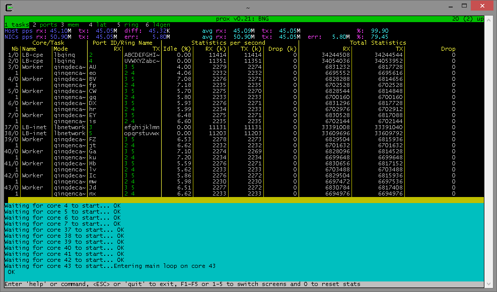
Packet pROcessing eXecution Engine (PROX) which is a DPDK application. PROX can do operations on packets in a highly configurable manner. The PROX application is also displaying performance statistics that can be used for performance investigations. Intel® DPPD - PROX is an application built on top of DPDK which allows creating software architectures, such as the one depicted below, through small and readable configuration files.
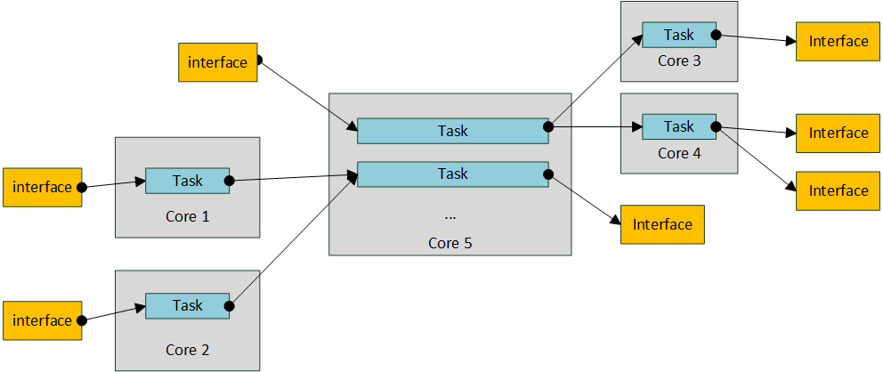
The figure shows that each core is executing a set of tasks. Currently, a task can be any one of the following:
- Classify
- Drop
- Basic Forwarding (no touch)
- L2 Forwarding (change MAC)
- GRE encap/decap
- Load balance based on packet fields
- Symmetric load balancing
- QinQ encap/decap IPv4/IPv6
- ARP
- QoS
- Routing
- Unmpls
- Policing
- ACL ...
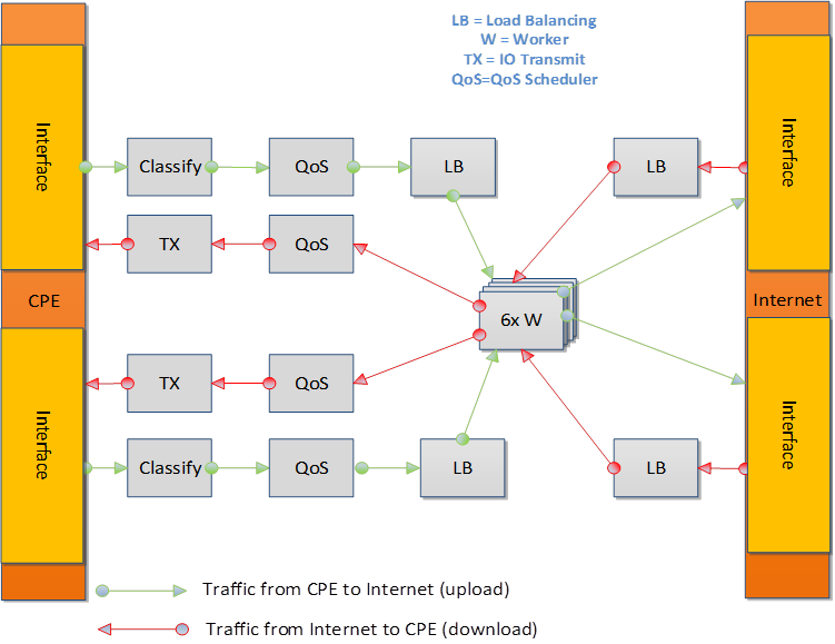
One of the example configurations that is distributed with the source code is a Proof of Concept (PoC) implementation of a Broadband Network Gateway (BNG) with Quality of Service (QoS). The software architecture for this PoC is presented below.
The display shows per task statistics through an ncurses interface. Statistics include: estimated idleness; per second statistics for packets received, transmitted or dropped; per core cache occupancy; cycles per packet. These statistics can help pinpoint bottlenecks in the system. This information can then be used to optimize the configuration. Other features include debugging support, scripting, Open vSwitch support... A screenshot of the display is provided below.