VSPERF
VSPERF is an OPNFV testing project.
VSPERF will develop a generic and architecture agnostic vSwitch testing framework and associated tests, that will serve as a basis for validating the suitability of different vSwitch implementations in a Telco NFV deployment environment. The output of this project will be utilized by the OPNFV Performance and Test group and its associated projects, as part of OPNFV Platform and VNF level testing and validation.
- Project Wiki: https://wiki.opnfv.org/characterize_vswitch_performance_for_telco_nfv_use_cases
- Project Repository: https://gerrit.opnfv.org/gerrit/#/q/vswitchperf
- Continuous Integration https://build.opnfv.org/ci/view/vswitchperf/
1. VSPERF Installation Guide
1.1. Installing vswitchperf
1.1.1. Supported Operating Systems
- CentOS 7
- Fedora 20
- Fedora 21
- Fedora 22
- RedHat 7.2
- Ubuntu 14.04
1.1.2. Supported vSwitches
The vSwitch must support Open Flow 1.3 or greater.
- OVS (built from source).
- OVS with DPDK (built from source).
1.1.3. Supported Hypervisors
- Qemu version 2.3.
1.1.4. Available VNFs
A simple VNF that forwards traffic through a VM, using:
- DPDK testpmd
- Linux Brigde
- custom l2fwd module
The official VM image is called vloop-vnf and it is available for free download at OPNFV website.
1.1.4.1. vloop-vnf changelog:
- vloop-vnf-ubuntu-14.04_20160804
- Linux kernel 4.4.0 installed
- libnuma-dev installed
- security updates applied
- vloop-vnf-ubuntu-14.04_20160303
- snmpd service is disabled by default to avoid error messages during VM boot
- security updates applied
- vloop-vnf-ubuntu-14.04_20151216
- version with development tools required for build of DPDK and l2fwd
1.1.5. Other Requirements
The test suite requires Python 3.3 and relies on a number of other packages. These need to be installed for the test suite to function.
Installation of required packages, preparation of Python 3 virtual environment and compilation of OVS, DPDK and QEMU is performed by script systems/build_base_machine.sh. It should be executed under user account, which will be used for vsperf execution.
Please Note: Password-less sudo access must be configured for given user account before script is executed.
Execution of installation script:
$ cd systems
$ ./build_base_machine.sh
Please Note: you don’t need to go into any of the systems subdirectories, simply run the top level build_base_machine.sh, your OS will be detected automatically.
Script build_base_machine.sh will install all the vsperf dependencies in terms of system packages, Python 3.x and required Python modules. In case of CentOS 7 it will install Python 3.3 from an additional repository provided by Software Collections (a link). In case of RedHat 7 it will install Python 3.4 as an alternate installation in /usr/local/bin. Installation script will also use virtualenv to create a vsperf virtual environment, which is isolated from the default Python environment. This environment will reside in a directory called vsperfenv in $HOME.
You will need to activate the virtual environment every time you start a new shell session. Its activation is specific to your OS:
1.1.5.1. CentOS 7
$ scl enable python33 bash
$ cd $HOME/vsperfenv
$ source bin/activate
1.1.5.2. Fedora, RedHat and Ubuntu
$ cd $HOME/vsperfenv
$ source bin/activate
1.1.5.2.1. Gotcha
$ source bin/activate
Badly placed ()'s.
Check what type of shell you are using
echo $shell
/bin/tcsh
See what scripts are available in $HOME/vsperfenv/bin
$ ls bin/
activate          activate.csh      activate.fish     activate_this.py
source the appropriate script
$ source bin/activate.csh
1.1.5.3. Working Behind a Proxy
If you’re behind a proxy, you’ll likely want to configure this before running any of the above. For example:
export http_proxy=proxy.mycompany.com:123
export https_proxy=proxy.mycompany.com:123
1.1.6. Hugepage Configuration
Systems running vsperf with either dpdk and/or tests with guests must configure hugepage amounts to support running these configurations. It is recommended to configure 1GB hugepages as the pagesize.
The amount of hugepages needed depends on your configuration files in vsperf.
Each guest image requires 4096 MB by default according to the default settings
in the 04_vnf.conf file.
GUEST_MEMORY = ['4096', '4096']
The dpdk startup parameters also require an amount of hugepages depending on
your configuration in the 02_vswitch.conf file.
VSWITCHD_DPDK_ARGS = ['-c', '0x4', '-n', '4', '--socket-mem 1024,1024']
VSWITCHD_DPDK_CONFIG = {
    'dpdk-init' : 'true',
    'dpdk-lcore-mask' : '0x4',
    'dpdk-socket-mem' : '1024,1024',
}
Note: Option VSWITCHD_DPDK_ARGS is used for vswitchd, which supports –dpdk parameter. In recent vswitchd versions, option VSWITCHD_DPDK_CONFIG will be used to configure vswitchd via ovs-vsctl calls.
With the –socket-mem argument set to use 1 hugepage on the specified sockets as seen above, the configuration will need 10 hugepages total to run all tests within vsperf if the pagesize is set correctly to 1GB.
VSPerf will verify hugepage amounts are free before executing test environments. In case of hugepage amounts not being free, test initialization will fail and testing will stop.
Please Note: In some instances on a test failure dpdk resources may not release hugepages used in dpdk configuration. It is recommended to configure a few extra hugepages to prevent a false detection by VSPerf that not enough free hugepages are available to execute the test environment. Normally dpdk would use previously allocated hugepages upon initialization.
Depending on your OS selection configuration of hugepages may vary. Please refer to your OS documentation to set hugepages correctly. It is recommended to set the required amount of hugepages to be allocated by default on reboots.
Information on hugepage requirements for dpdk can be found at http://dpdk.org/doc/guides/linux_gsg/sys_reqs.html
You can review your hugepage amounts by executing the following command
cat /proc/meminfo | grep Huge
If no hugepages are available vsperf will try to automatically allocate some.
Allocation is controlled by HUGEPAGE_RAM_ALLOCATION configuration parameter in
02_vswitch.conf file. Default is 2GB, resulting in either 2 1GB hugepages
or 1024 2MB hugepages.
1.2. ‘vsperf’ Traffic Gen Guide
1.2.1. Overview
VSPERF supports the following traffic generators:
- Dummy (DEFAULT): Allows you to use your own external traffic generator.
- IXIA (IxNet and IxOS)
- Spirent TestCenter
- Xena Networks
- MoonGen
To see the list of traffic gens from the cli:
$ ./vsperf --list-trafficgens
This guide provides the details of how to install and configure the various traffic generators.
1.2.2. Background Information
The traffic default configuration can be found in tools/pkt_gen/trafficgen/trafficgenhelper.py, and is configured as follows:
TRAFFIC_DEFAULTS = {
    'l2': {
        'framesize': 64,
        'srcmac': '00:00:00:00:00:00',
        'dstmac': '00:00:00:00:00:00',
    },
    'l3': {
        'proto': 'tcp',
        'srcip': '1.1.1.1',
        'dstip': '90.90.90.90',
    },
    'l4': {
        'srcport': 3000,
        'dstport': 3001,
    },
    'vlan': {
        'enabled': False,
        'id': 0,
        'priority': 0,
        'cfi': 0,
    },
}
The framesize parameter can be overridden from the configuration
files by adding the following to your custom configuration file
10_custom.conf:
TRAFFICGEN_PKT_SIZES = (64, 128,)
OR from the commandline:
$ ./vsperf --test-params "pkt_sizes=x,y" $TESTNAME
You can also modify the traffic transmission duration and the number of tests run by the traffic generator by extending the example commandline above to:
$ ./vsperf --test-params "pkt_sizes=x,y;duration=10;rfc2544_tests=1" $TESTNAME
1.2.3. Dummy Setup
To select the Dummy generator please add the following to your
custom configuration file 10_custom.conf.
TRAFFICGEN = 'Dummy'
OR run vsperf with the --trafficgen argument
$ ./vsperf --trafficgen Dummy $TESTNAME
Where $TESTNAME is the name of the vsperf test you would like to run. This will setup the vSwitch and the VNF (if one is part of your test) print the traffic configuration and prompt you to transmit traffic when the setup is complete.
Please send 'continuous' traffic with the following stream config:
30mS, 90mpps, multistream False
and the following flow config:
{
    "flow_type": "port",
    "l3": {
        "srcip": "1.1.1.1",
        "proto": "tcp",
        "dstip": "90.90.90.90"
    },
    "traffic_type": "continuous",
    "multistream": 0,
    "bidir": "True",
    "vlan": {
        "cfi": 0,
        "priority": 0,
        "id": 0,
        "enabled": false
    },
    "frame_rate": 90,
    "l2": {
        "dstport": 3001,
        "srcport": 3000,
        "dstmac": "00:00:00:00:00:00",
        "srcmac": "00:00:00:00:00:00",
        "framesize": 64
    }
}
What was the result for 'frames tx'?
When your traffic gen has completed traffic transmission and provided the results please input these at the vsperf prompt. vsperf will try to verify the input:
Is '$input_value' correct?
Please answer with y OR n.
- VPSERF will ask you for:
- Result for ‘frames tx’
- Result for ‘frames rx’
- Result for ‘min latency’
- Result for ‘max latency’
- Result for ‘avg latency’
Finally vsperf will print out the results for your test and generate the appropriate logs and csv files.
1.2.4. IXIA Setup
1.2.4.1. On the CentOS 7 system
You need to install IxNetworkTclClient$(VER_NUM)Linux.bin.tgz.
1.2.4.2. On the IXIA client software system
Find the IxNetwork TCL server app (start -> All Programs -> IXIA -> IxNetwork -> IxNetwork_$(VER_NUM) -> IxNetwork TCL Server)
Right click on IxNetwork TCL Server, select properties - Under shortcut tab in the Target dialogue box make sure there is the argument “-tclport xxxx” where xxxx is your port number (take note of this port number as you will need it for the 10_custom.conf file).
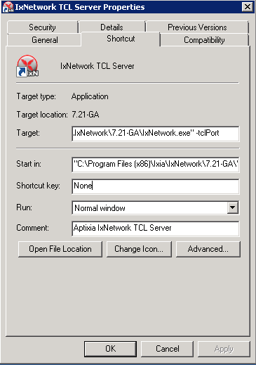
Hit Ok and start the TCL server application
1.2.4.3. VSPERF configuration
There are several configuration options specific to the IxNetworks traffic generator from IXIA. It is essential to set them correctly, before the VSPERF is executed for the first time.
Detailed description of options follows:
- TRAFFICGEN_IXNET_MACHINE - IP address of server, where IxNetwork TCL Server is running
- TRAFFICGEN_IXNET_PORT - PORT, where IxNetwork TCL Server is accepting connections from TCL clients
- TRAFFICGEN_IXNET_USER - username, which will be used during communication with IxNetwork TCL Server and IXIA chassis
- TRAFFICGEN_IXIA_HOST - IP address of IXIA traffic generator chassis
- TRAFFICGEN_IXIA_CARD - identification of card with dedicated ports at IXIA chassis
- TRAFFICGEN_IXIA_PORT1 - identification of the first dedicated port at TRAFFICGEN_IXIA_CARD at IXIA chassis; VSPERF uses two separated ports for traffic generation. In case of unidirectional traffic, it is essential to correctly connect 1st IXIA port to the 1st NIC at DUT, i.e. to the first PCI handle from WHITELIST_NICS list. Otherwise traffic may not be able to pass through the vSwitch.
- TRAFFICGEN_IXIA_PORT2 - identification of the second dedicated port at TRAFFICGEN_IXIA_CARD at IXIA chassis; VSPERF uses two separated ports for traffic generation. In case of unidirectional traffic, it is essential to correctly connect 2nd IXIA port to the 2nd NIC at DUT, i.e. to the second PCI handle from WHITELIST_NICS list. Otherwise traffic may not be able to pass through the vSwitch.
- TRAFFICGEN_IXNET_LIB_PATH - path to the DUT specific installation of IxNetwork TCL API
- TRAFFICGEN_IXNET_TCL_SCRIPT - name of the TCL script, which VSPERF will use for communication with IXIA TCL server
- TRAFFICGEN_IXNET_TESTER_RESULT_DIR - folder accessible from IxNetwork TCL server, where test results are stored, e.g.
c:/ixia_results; see test-results-share- TRAFFICGEN_IXNET_DUT_RESULT_DIR - directory accessible from the DUT, where test results from IxNetwork TCL server are stored, e.g.
/mnt/ixia_results; see test-results-share
1.2.5. Spirent Setup
Spirent installation files and instructions are available on the Spirent support website at:
Select a version of Spirent TestCenter software to utilize. This example will use Spirent TestCenter v4.57 as an example. Substitute the appropriate version in place of ‘v4.57’ in the examples, below.
1.2.5.1. On the CentOS 7 System
Download and install the following:
Spirent TestCenter Application, v4.57 for 64-bit Linux Client
1.2.5.2. Spirent Virtual Deployment Service (VDS)
Spirent VDS is required for both TestCenter hardware and virtual chassis in the vsperf environment. For installation, select the version that matches the Spirent TestCenter Application version. For v4.57, the matching VDS version is 1.0.55. Download either the ova (VMware) or qcow2 (QEMU) image and create a VM with it. Initialize the VM according to Spirent installation instructions.
1.2.5.3. Using Spirent TestCenter Virtual (STCv)
STCv is available in both ova (VMware) and qcow2 (QEMU) formats. For VMware, download:
Spirent TestCenter Virtual Machine for VMware, v4.57 for Hypervisor - VMware ESX.ESXi
Virtual test port performance is affected by the hypervisor configuration. For best practice results in deploying STCv, the following is suggested:
- Create a single VM with two test ports rather than two VMs with one port each
- Set STCv in DPDK mode
- Give STCv 2*n + 1 cores, where n = the number of ports. For vsperf, cores = 5.
- Turning off hyperthreading and pinning these cores will improve performance
- Give STCv 2 GB of RAM
To get the highest performance and accuracy, Spirent TestCenter hardware is recommended. vsperf can run with either stype test ports.
1.2.5.4. Using STC REST Client
The stcrestclient package provides the stchttp.py ReST API wrapper module. This allows simple function calls, nearly identical to those provided by StcPython.py, to be used to access TestCenter server sessions via the STC ReST API. Basic ReST functionality is provided by the resthttp module, and may be used for writing ReST clients independent of STC.
- Project page: <https://github.com/Spirent/py-stcrestclient>
- Package download: <http://pypi.python.org/pypi/stcrestclient>
To use REST interface, follow the instructions in the Project page to install the package. Once installed, the scripts named with ‘rest’ keyword can be used. For example: testcenter-rfc2544-rest.py can be used to run RFC 2544 tests using the REST interface.
1.2.6. Xena Networks
1.2.6.1. Installation
Xena Networks traffic generator requires specific files and packages to be installed. It is assumed the user has access to the Xena2544.exe file which must be placed in VSPerf installation location under the tools/pkt_gen/xena folder. Contact Xena Networks for the latest version of this file. The user can also visit www.xenanetworks/downloads to obtain the file with a valid support contract.
Note VSPerf has been fully tested with version v2.43 of Xena2544.exe
To execute the Xena2544.exe file under Linux distributions the mono-complete package must be installed. To install this package follow the instructions below. Further information can be obtained from http://www.mono-project.com/docs/getting-started/install/linux/
rpm --import "http://keyserver.ubuntu.com/pks/lookup?op=get&search=0x3FA7E0328081BFF6A14DA29AA6A19B38D3D831EF"
yum-config-manager --add-repo http://download.mono-project.com/repo/centos/
yum -y install mono-complete
To prevent gpg errors on future yum installation of packages the mono-project repo should be disabled once installed.
yum-config-manager --disable download.mono-project.com_repo_centos_
1.2.6.2. Configuration
Connection information for your Xena Chassis must be supplied inside the
10_custom.conf or 03_custom.conf file. The following parameters must be
set to allow for proper connections to the chassis.
TRAFFICGEN_XENA_IP = ''
TRAFFICGEN_XENA_PORT1 = ''
TRAFFICGEN_XENA_PORT2 = ''
TRAFFICGEN_XENA_USER = ''
TRAFFICGEN_XENA_PASSWORD = ''
TRAFFICGEN_XENA_MODULE1 = ''
TRAFFICGEN_XENA_MODULE2 = ''
1.2.6.3. RFC2544 Throughput Testing
Xena traffic generator testing for rfc2544 throughput can be modified for different behaviors if needed. The default options for the following are optimized for best results.
TRAFFICGEN_XENA_2544_TPUT_INIT_VALUE = '10.0'
TRAFFICGEN_XENA_2544_TPUT_MIN_VALUE = '0.1'
TRAFFICGEN_XENA_2544_TPUT_MAX_VALUE = '100.0'
TRAFFICGEN_XENA_2544_TPUT_VALUE_RESOLUTION = '0.5'
TRAFFICGEN_XENA_2544_TPUT_USEPASS_THRESHHOLD = 'false'
TRAFFICGEN_XENA_2544_TPUT_PASS_THRESHHOLD = '0.0'
Each value modifies the behavior of rfc 2544 throughput testing. Refer to your Xena documentation to understand the behavior changes in modifying these values.
1.2.7. MoonGen
1.2.7.1. Installation
MoonGen architecture overview and general installation instructions can be found here:
https://github.com/emmericp/MoonGen
- Note: Today, MoonGen with VSPERF only supports 10Gbps line speeds.
For VSPerf use, MoonGen should be cloned from here (as opposed to the previously mentioned GitHub):
git clone https://github.com/atheurer/MoonGen
and use the opnfv-stable branch:
git checkout opnfv-stable
VSPerf uses a particular example script under the examples directory within the MoonGen project:
MoonGen/examples/opnfv-vsperf.lua
Follow MoonGen set up instructions here:
https://github.com/atheurer/MoonGen/blob/opnfv-stable/MoonGenSetUp.html
Note one will need to set up ssh login to not use passwords between the server running MoonGen and the device under test (running the VSPERF test infrastructure). This is because VSPERF on one server uses ‘ssh’ to configure and run MoonGen upon the other server.
One can set up this ssh access by doing the following on both servers:
ssh-keygen -b 2048 -t rsa
ssh-copy-id <other server>
1.2.7.2. Configuration
Connection information for your Xena Chassis must be supplied inside the
10_custom.conf or 03_custom.conf file. The following parameters must be
set to allow for proper connections to the chassis.
TRAFFICGEN_MOONGEN_HOST_IP_ADDR = ""
TRAFFICGEN_MOONGEN_USER = ""
TRAFFICGEN_MOONGEN_BASE_DIR = ""
TRAFFICGEN_MOONGEN_PORTS = ""
TRAFFICGEN_MOONGEN_LINE_SPEED_GBPS = ""
2. VSPERF User Guide
2.1. vSwitchPerf test suites userguide
2.1.1. General
VSPERF requires a traffic generators to run tests, automated traffic gen support in VSPERF includes:
- IXIA traffic generator (IxNetwork hardware) and a machine that runs the IXIA client software.
- Spirent traffic generator (TestCenter hardware chassis or TestCenter virtual in a VM) and a VM to run the Spirent Virtual Deployment Service image, formerly known as “Spirent LabServer”.
- Xena Network traffic generator (Xena hardware chassis) that houses the Xena Traffic generator modules.
- Moongen software traffic generator. Requires a separate machine running moongen to execute packet generation.
If you want to use another traffic generator, please select the Dummy generator option as shown in Traffic generator instructions
2.1.2. VSPERF Installation
To see the supported Operating Systems, vSwitches and system requirements, please follow the installation instructions to install.
2.1.3. Traffic Generator Setup
Follow the Traffic generator instructions to install and configure a suitable traffic generator.
2.1.4. Cloning and building src dependencies
In order to run VSPERF, you will need to download DPDK and OVS. You can do this manually and build them in a preferred location, OR you could use vswitchperf/src. The vswitchperf/src directory contains makefiles that will allow you to clone and build the libraries that VSPERF depends on, such as DPDK and OVS. To clone and build simply:
$ cd src
$ make
VSPERF can be used with stock OVS (without DPDK support). When build is finished, the libraries are stored in src_vanilla directory.
The ‘make’ builds all options in src:
- Vanilla OVS
- OVS with vhost_user as the guest access method (with DPDK support)
- OVS with vhost_cuse s the guest access method (with DPDK support)
The vhost_user build will reside in src/ovs/ The vhost_cuse build will reside in vswitchperf/src_cuse The Vanilla OVS build will reside in vswitchperf/src_vanilla
To delete a src subdirectory and its contents to allow you to re-clone simply use:
$ make clobber
2.1.5. Configure the ./conf/10_custom.conf file
The 10_custom.conf file is the configuration file that overrides
default configurations in all the other configuration files in ./conf
The supplied 10_custom.conf file MUST be modified, as it contains
configuration items for which there are no reasonable default values.
The configuration items that can be added is not limited to the initial
contents. Any configuration item mentioned in any .conf file in
./conf directory can be added and that item will be overridden by
the custom configuration value.
2.1.6. Using a custom settings file
If your 10_custom.conf doesn’t reside in the ./conf directory
of if you want to use an alternative configuration file, the file can
be passed to vsperf via the --conf-file argument.
$ ./vsperf --conf-file <path_to_custom_conf> ...
Note that configuration passed in via the environment (--load-env)
or via another command line argument will override both the default and
your custom configuration files. This “priority hierarchy” can be
described like so (1 = max priority):
- Command line arguments
- Environment variables
- Configuration file(s)
2.1.7. vloop_vnf
vsperf uses a VM called vloop_vnf for looping traffic in the PVP and PVVP deployment scenarios. The image can be downloaded from http://artifacts.opnfv.org/.
$ wget http://artifacts.opnfv.org/vswitchperf/vloop-vnf-ubuntu-14.04_20151216.qcow2
Newer vloop_vnf images are available. Please reference the installation instructions for information on these images installation instructions
vloop_vnf forwards traffic through a VM using one of: * DPDK testpmd * Linux Bridge * l2fwd kernel Module.
Alternatively you can use your own QEMU image.
2.1.8. l2fwd Kernel Module
A Kernel Module that provides OSI Layer 2 Ipv4 termination or forwarding with support for Destination Network Address Translation (DNAT) for both the MAC and IP addresses. l2fwd can be found in <vswitchperf_dir>/src/l2fwd
2.1.9. Executing tests
Before running any tests make sure you have root permissions by adding the following line to /etc/sudoers:
username ALL=(ALL) NOPASSWD: ALL
username in the example above should be replaced with a real username.
To list the available tests:
$ ./vsperf --list
To run a single test:
$ ./vsperf $TESTNAME
Where $TESTNAME is the name of the vsperf test you would like to run.
To run a group of tests, for example all tests with a name containing ‘RFC2544’:
$ ./vsperf --conf-file=<path_to_custom_conf>/10_custom.conf --tests="RFC2544"
To run all tests:
$ ./vsperf --conf-file=<path_to_custom_conf>/10_custom.conf
Some tests allow for configurable parameters, including test duration (in seconds) as well as packet sizes (in bytes).
$ ./vsperf --conf-file user_settings.py
    --tests RFC2544Tput
    --test-params "duration=10;pkt_sizes=128"
For all available options, check out the help dialog:
$ ./vsperf --help
2.1.10. Executing Vanilla OVS tests
- If needed, recompile src for all OVS variants
$ cd src
$ make distclean
$ make
2. Update your ‘‘10_custom.conf’’ file to use the appropriate variables for Vanilla OVS:
VSWITCH = 'OvsVanilla'
Where $PORT1 and $PORT2 are the Linux interfaces you’d like to bind to the vswitch.
- Run test:
$ ./vsperf --conf-file=<path_to_custom_conf>
Please note if you don’t want to configure Vanilla OVS through the configuration file, you can pass it as a CLI argument; BUT you must set the ports.
$ ./vsperf --vswitch OvsVanilla
2.1.11. Executing PVP and PVVP tests
To run tests using vhost-user as guest access method:
- Set VHOST_METHOD and VNF of your settings file to:
VHOST_METHOD='user'
VNF = 'QemuDpdkVhost'
- If needed, recompile src for all OVS variants
$ cd src
$ make distclean
$ make
- Run test:
$ ./vsperf --conf-file=<path_to_custom_conf>/10_custom.conf
To run tests using vhost-cuse as guest access method:
- Set VHOST_METHOD and VNF of your settings file to:
VHOST_METHOD='cuse'
VNF = 'QemuDpdkVhostCuse'
- If needed, recompile src for all OVS variants
$ cd src
$ make distclean
$ make
- Run test:
$ ./vsperf --conf-file=<path_to_custom_conf>/10_custom.conf
2.1.12. Executing PVP tests using Vanilla OVS
To run tests using Vanilla OVS:
- Set the following variables:
VSWITCH = 'OvsVanilla'
VNF = 'QemuVirtioNet'

VANILLA_TGEN_PORT1_IP = n.n.n.n
VANILLA_TGEN_PORT1_MAC = nn:nn:nn:nn:nn:nn

VANILLA_TGEN_PORT2_IP = n.n.n.n
VANILLA_TGEN_PORT2_MAC = nn:nn:nn:nn:nn:nn

VANILLA_BRIDGE_IP = n.n.n.n

or use --test-param

$ ./vsperf --conf-file=<path_to_custom_conf>/10_custom.conf
           --test-params "vanilla_tgen_tx_ip=n.n.n.n;
                         vanilla_tgen_tx_mac=nn:nn:nn:nn:nn:nn"
- If needed, recompile src for all OVS variants
$ cd src
$ make distclean
$ make
- Run test:
$ ./vsperf --conf-file<path_to_custom_conf>/10_custom.conf
2.1.13. Using vfio_pci with DPDK
To use vfio with DPDK instead of igb_uio edit ‘conf/02_vswitch.conf’ with the following parameters:
DPDK_MODULES = [
 ('vfio-pci'),
]
SYS_MODULES = ['cuse']
NOTE: Please ensure that Intel VT-d is enabled in BIOS.
NOTE: Please ensure your boot/grub parameters include the following:
iommu=pt intel_iommu=on
To check that IOMMU is enabled on your platform:
$ dmesg | grep IOMMU
[    0.000000] Intel-IOMMU: enabled
[    0.139882] dmar: IOMMU 0: reg_base_addr fbffe000 ver 1:0 cap d2078c106f0466 ecap f020de
[    0.139888] dmar: IOMMU 1: reg_base_addr ebffc000 ver 1:0 cap d2078c106f0466 ecap f020de
[    0.139893] IOAPIC id 2 under DRHD base  0xfbffe000 IOMMU 0
[    0.139894] IOAPIC id 0 under DRHD base  0xebffc000 IOMMU 1
[    0.139895] IOAPIC id 1 under DRHD base  0xebffc000 IOMMU 1
[    3.335744] IOMMU: dmar0 using Queued invalidation
[    3.335746] IOMMU: dmar1 using Queued invalidation
....
2.1.14. Using SRIOV support
To use virtual functions of NIC with SRIOV support, use extended form of NIC PCI slot definition:
WHITELIST_NICS = ['0000:05:00.0|vf0', '0000:05:00.1|vf3']
Where ‘vf’ is an indication of virtual function usage and following number defines a VF to be used. In case that VF usage is detected, then vswitchperf will enable SRIOV support for given card and it will detect PCI slot numbers of selected VFs.
So in example above, one VF will be configured for NIC ‘0000:05:00.0’ and four VFs will be configured for NIC ‘0000:05:00.1’. Vswitchperf will detect PCI addresses of selected VFs and it will use them during test execution.
At the end of vswitchperf execution, SRIOV support will be disabled.
SRIOV support is generic and it can be used in different testing scenarios. For example:
- vSwitch tests with DPDK or without DPDK support to verify impact of VF usage on vSwitch performance
- tests without vSwitch, where traffic is forwared directly between VF interfaces by packet forwarder (e.g. testpmd application)
- tests without vSwitch, where VM accesses VF interfaces directly by PCI-passthrough to measure raw VM throughput performance.
2.1.15. Using QEMU with PCI passthrough support
Raw virtual machine throughput performance can be measured by execution of PVP test with direct access to NICs by PCI passthrough. To execute VM with direct access to PCI devices, enable vfio-pci. In order to use virtual functions, SRIOV-support must be enabled.
Execution of test with PCI passthrough with vswitch disabled:
$ ./vsperf --conf-file=<path_to_custom_conf>/10_custom.conf
           --vswitch none --vnf QemuPciPassthrough pvp_tput
Any of supported guest-loopback-application can be used inside VM with PCI passthrough support.
Note: Qemu with PCI passthrough support can be used only with PVP test deployment.
2.1.16. Selection of loopback application for PVP and PVVP tests
To select loopback application, which will perform traffic forwarding inside VM, following configuration parameter should be configured:
GUEST_LOOPBACK = ['testpmd', 'testpmd']
or use –test-param
$ ./vsperf --conf-file=<path_to_custom_conf>/10_custom.conf
      --test-params "guest_loopback=testpmd"
Supported loopback applications are:
'testpmd'       - testpmd from dpdk will be built and used
'l2fwd'         - l2fwd module provided by Huawei will be built and used
'linux_bridge'  - linux bridge will be configured
'buildin'       - nothing will be configured by vsperf; VM image must
                  ensure traffic forwarding between its interfaces
Guest loopback application must be configured, otherwise traffic will not be forwarded by VM and testcases with PVP and PVVP deployments will fail. Guest loopback application is set to ‘testpmd’ by default.
2.1.17. Multi-Queue Configuration
VSPerf currently supports multi-queue with the following limitations:
- Execution of pvp/pvvp tests require testpmd as the loopback if multi-queue is enabled at the guest.
- Requires QemuDpdkVhostUser as the vnf.
- Requires switch to be set to OvsDpdkVhost.
- Requires QEMU 2.5 or greater and any OVS version higher than 2.5. The default upstream package versions installed by VSPerf satisfy this requirement.
To enable multi-queue modify the ‘‘02_vswitch.conf’’ file to enable multi-queue on the switch.
VSWITCH_MULTI_QUEUES = 2
NOTE: you should consider using the switch affinity to set a pmd cpu mask that can optimize your performance. Consider the numa of the NIC in use if this applies by checking /sys/class/net/<eth_name>/device/numa_node and setting an appropriate mask to create PMD threads on the same numa node.
When multi-queue is enabled, each dpdk or dpdkvhostuser port that is created on the switch will set the option for multiple queues.
To enable multi-queue on the guest modify the ‘‘04_vnf.conf’’ file.
GUEST_NIC_QUEUES = 2
Enabling multi-queue at the guest will add multiple queues to each NIC port when qemu launches the guest.
Testpmd should be configured to take advantage of multi-queue on the guest. This can be done by modifying the ‘‘04_vnf.conf’’ file.
GUEST_TESTPMD_CPU_MASK = '-l 0,1,2,3,4'

GUEST_TESTPMD_NB_CORES = 4
GUEST_TESTPMD_TXQ = 2
GUEST_TESTPMD_RXQ = 2
NOTE: The guest SMP cores must be configured to allow for testpmd to use the optimal number of cores to take advantage of the multiple guest queues.
NOTE: For optimal performance guest SMPs should be on the same numa as the NIC in use if possible/applicable. Testpmd should be assigned at least (nb_cores +1) total cores with the cpu mask.
2.1.18. Executing Packet Forwarding tests
To select application, which will perform packet forwarding, following configuration parameter should be configured:
VSWITCH = 'none'
PKTFWD = 'TestPMD'

or use --vswitch and --fwdapp

$ ./vsperf --conf-file user_settings.py
         --vswitch none
         --fwdapp TestPMD
Supported Packet Forwarding applications are:
'testpmd' - testpmd from dpdk
1. Update your ‘‘10_custom.conf’’ file to use the appropriate variables for selected Packet Forwarder:
# testpmd configuration
TESTPMD_ARGS = []
# packet forwarding mode supported by testpmd; Please see DPDK documentation
# for comprehensive list of modes supported by your version.
# e.g. io|mac|mac_retry|macswap|flowgen|rxonly|txonly|csum|icmpecho|...
# Note: Option "mac_retry" has been changed to "mac retry" since DPDK v16.07
TESTPMD_FWD_MODE = 'csum'
# checksum calculation layer: ip|udp|tcp|sctp|outer-ip
TESTPMD_CSUM_LAYER = 'ip'
# checksum calculation place: hw (hardware) | sw (software)
TESTPMD_CSUM_CALC = 'sw'
# recognize tunnel headers: on|off
TESTPMD_CSUM_PARSE_TUNNEL = 'off'
- Run test:
$ ./vsperf --conf-file <path_to_settings_py>
2.1.19. VSPERF modes of operation
VSPERF can be run in different modes. By default it will configure vSwitch, traffic generator and VNF. However it can be used just for configuration and execution of traffic generator. Another option is execution of all components except traffic generator itself.
Mode of operation is driven by configuration parameter -m or –mode
-m MODE, --mode MODE  vsperf mode of operation;
    Values:
        "normal" - execute vSwitch, VNF and traffic generator
        "trafficgen" - execute only traffic generator
        "trafficgen-off" - execute vSwitch and VNF
        "trafficgen-pause" - execute vSwitch and VNF but wait before traffic transmission
In case, that VSPERF is executed in “trafficgen” mode, then configuration of traffic generator should be configured through –test-params option. Supported CLI options useful for traffic generator configuration are:
'traffic_type'  - One of the supported traffic types. E.g. rfc2544,
                  back2back or continuous
                  Default value is "rfc2544".
'bidirectional' - Specifies if generated traffic will be full-duplex (true)
                  or half-duplex (false)
                  Default value is "false".
'iload'         - Defines desired percentage of frame rate used during
                  continuous stream tests.
                  Default value is 100.
'multistream'   - Defines number of flows simulated by traffic generator.
                  Value 0 disables MultiStream feature
                  Default value is 0.
'stream_type'   - Stream Type is an extension of the "MultiStream" feature.
                  If MultiStream is disabled, then Stream Type will be
                  ignored. Stream Type defines ISO OSI network layer used
                  for simulation of multiple streams.
                  Default value is "L4".
Example of execution of VSPERF in “trafficgen” mode:
$ ./vsperf -m trafficgen --trafficgen IxNet --conf-file vsperf.conf
    --test-params "traffic_type=continuous;bidirectional=True;iload=60"
2.1.20. Code change verification by pylint
Every developer participating in VSPERF project should run pylint before his python code is submitted for review. Project specific configuration for pylint is available at ‘pylint.rc’.
Example of manual pylint invocation:
$ pylint --rcfile ./pylintrc ./vsperf
2.1.21. GOTCHAs:
2.1.21.1. OVS with DPDK and QEMU
If you encounter the following error: “before (last 100 chars): ‘-path=/dev/hugepages,share=on: unable to map backing store for hugepages: Cannot allocate memoryrnrn” with the PVP or PVVP deployment scenario, check the amount of hugepages on your system:
$ cat /proc/meminfo | grep HugePages
By default the vswitchd is launched with 1Gb of memory, to change this, modify –socket-mem parameter in conf/02_vswitch.conf to allocate an appropriate amount of memory:
VSWITCHD_DPDK_ARGS = ['-c', '0x4', '-n', '4', '--socket-mem 1024,0']
VSWITCHD_DPDK_CONFIG = {
    'dpdk-init' : 'true',
    'dpdk-lcore-mask' : '0x4',
    'dpdk-socket-mem' : '1024,0',
}
Note: Option VSWITCHD_DPDK_ARGS is used for vswitchd, which supports –dpdk parameter. In recent vswitchd versions, option VSWITCHD_DPDK_CONFIG will be used to configure vswitchd via ovs-vsctl calls.
2.1.22. More information
For more information and details refer to the vSwitchPerf user guide at: http://artifacts.opnfv.org/vswitchperf/docs/userguide/index.html
2.2. Integration tests
VSPERF includes a set of integration tests defined in conf/integration. These tests can be run by specifying –integration as a parameter to vsperf. Current tests in conf/integration include switch functionality and Overlay tests.
Tests in the conf/integration can be used to test scaling of different switch configurations by adding steps into the test case.
For the overlay tests VSPERF supports VXLAN, GRE and GENEVE tunneling protocols. Testing of these protocols is limited to unidirectional traffic and P2P (Physical to Physical scenarios).
NOTE: The configuration for overlay tests provided in this guide is for unidirectional traffic only.
2.2.1. Executing Integration Tests
To execute integration tests VSPERF is run with the integration parameter. To view the current test list simply execute the following command:
./vsperf --integration --list
The standard tests included are defined inside the
conf/integration/01_testcases.conf file.
2.2.2. Test Steps
Execution of integration tests are done on a step by step work flow starting with step 0 as defined inside the test case. Each step of the test increments the step number by one which is indicated in the log.
(testcases.integration) - Step 1 - 'vswitch add_switch ['int_br1']' ... OK
Each step in the test case is validated. If a step does not pass validation the test will fail and terminate. The test will continue until a failure is detected or all steps pass. A csv report file is generated after a test completes with an OK or FAIL result.
2.2.3. Test Macros
Test profiles can include macros as part of the test step. Each step in the profile may return a value such as a port name. Recall macros use #STEP to indicate the recalled value inside the return structure. If the method the test step calls returns a value it can be later recalled, for example:
{
    "Name": "vswitch_add_del_vport",
    "Deployment": "clean",
    "Description": "vSwitch - add and delete virtual port",
    "TestSteps": [
            ['vswitch', 'add_switch', 'int_br0'],               # STEP 0
            ['vswitch', 'add_vport', 'int_br0'],                # STEP 1
            ['vswitch', 'del_port', 'int_br0', '#STEP[1][0]'],  # STEP 2
            ['vswitch', 'del_switch', 'int_br0'],               # STEP 3
         ]
}
This test profile uses the vswitch add_vport method which returns a string value of the port added. This is later called by the del_port method using the name from step 1.
Also commonly used steps can be created as a separate profile.
STEP_VSWITCH_PVP_INIT = [
    ['vswitch', 'add_switch', 'int_br0'],           # STEP 0
    ['vswitch', 'add_phy_port', 'int_br0'],         # STEP 1
    ['vswitch', 'add_phy_port', 'int_br0'],         # STEP 2
    ['vswitch', 'add_vport', 'int_br0'],            # STEP 3
    ['vswitch', 'add_vport', 'int_br0'],            # STEP 4
]
This profile can then be used inside other testcases
{
    "Name": "vswitch_pvp",
    "Deployment": "clean",
    "Description": "vSwitch - configure switch and one vnf",
    "TestSteps": STEP_VSWITCH_PVP_INIT +
                 [
                    ['vnf', 'start'],
                    ['vnf', 'stop'],
                 ] +
                 STEP_VSWITCH_PVP_FINIT
}
2.2.4. HelloWorld and other basic Testcases
The following examples are for demonstration purposes. You can run them by copying and pasting into the conf/integration/01_testcases.conf file. A command-line instruction is shown at the end of each example.
2.2.4.1. HelloWorld
The first example is a HelloWorld testcase. It simply creates a bridge with 2 physical ports, then sets up a flow to drop incoming packets from the port that was instantiated at the STEP #1. There’s no interaction with the traffic generator. Then the flow, the 2 ports and the bridge are deleted. ‘add_phy_port’ method creates a ‘dpdk’ type interface that will manage the physical port. The string value returned is the port name that will be referred by ‘del_port’ later on.
{
    "Name": "HelloWorld",
    "Description": "My first testcase",
    "Deployment": "clean",
    "TestSteps": [
        ['vswitch', 'add_switch', 'int_br0'],   # STEP 0
        ['vswitch', 'add_phy_port', 'int_br0'], # STEP 1
        ['vswitch', 'add_phy_port', 'int_br0'], # STEP 2
        ['vswitch', 'add_flow', 'int_br0', {'in_port': '#STEP[1][1]', \
            'actions': ['drop'], 'idle_timeout': '0'}],
        ['vswitch', 'del_flow', 'int_br0'],
        ['vswitch', 'del_port', 'int_br0', '#STEP[1][0]'],
        ['vswitch', 'del_port', 'int_br0', '#STEP[2][0]'],
        ['vswitch', 'del_switch', 'int_br0'],
    ]

}
To run HelloWorld test:
./vsperf --conf-file user_settings.py --integration HelloWorld
2.2.4.2. Specify a Flow by the IP address
The next example shows how to explicitly set up a flow by specifying a destination IP address. All packets received from the port created at STEP #1 that have a destination IP address = 90.90.90.90 will be forwarded to the port created at the STEP #2.
{
    "Name": "p2p_rule_l3da",
    "Description": "Phy2Phy with rule on L3 Dest Addr",
    "Deployment": "clean",
    "biDirectional": "False",
    "TestSteps": [
        ['vswitch', 'add_switch', 'int_br0'],   # STEP 0
        ['vswitch', 'add_phy_port', 'int_br0'], # STEP 1
        ['vswitch', 'add_phy_port', 'int_br0'], # STEP 2
        ['vswitch', 'add_flow', 'int_br0', {'in_port': '#STEP[1][1]', \
            'dl_type': '0x0800', 'nw_dst': '90.90.90.90', \
            'actions': ['output:#STEP[2][1]'], 'idle_timeout': '0'}],
        ['trafficgen', 'send_traffic', {'traffic_type' : 'continuous'}],
        ['vswitch', 'dump_flows', 'int_br0'],   # STEP 5
        ['vswitch', 'del_flow', 'int_br0'],     # STEP 7 == del-flows
        ['vswitch', 'del_port', 'int_br0', '#STEP[1][0]'],
        ['vswitch', 'del_port', 'int_br0', '#STEP[2][0]'],
        ['vswitch', 'del_switch', 'int_br0'],
    ]
},
To run the test:
./vsperf --conf-file user_settings.py --integration p2p_rule_l3da
2.2.4.3. Multistream feature
The next testcase uses the multistream feature. The traffic generator will send packets with different UDP ports. That is accomplished by using “Stream Type” and “MultiStream” keywords. 4 different flows are set to forward all incoming packets.
{
    "Name": "multistream_l4",
    "Description": "Multistream on UDP ports",
    "Deployment": "clean",
    "Stream Type": "L4",
    "MultiStream": 4,
    "TestSteps": [
        ['vswitch', 'add_switch', 'int_br0'],   # STEP 0
        ['vswitch', 'add_phy_port', 'int_br0'], # STEP 1
        ['vswitch', 'add_phy_port', 'int_br0'], # STEP 2
        # Setup Flows
        ['vswitch', 'add_flow', 'int_br0', {'in_port': '#STEP[1][1]', \
            'dl_type': '0x0800', 'nw_proto': '17', 'udp_dst': '0', \
            'actions': ['output:#STEP[2][1]'], 'idle_timeout': '0'}],
        ['vswitch', 'add_flow', 'int_br0', {'in_port': '#STEP[1][1]', \
            'dl_type': '0x0800', 'nw_proto': '17', 'udp_dst': '1', \
            'actions': ['output:#STEP[2][1]'], 'idle_timeout': '0'}],
        ['vswitch', 'add_flow', 'int_br0', {'in_port': '#STEP[1][1]', \
            'dl_type': '0x0800', 'nw_proto': '17', 'udp_dst': '2', \
            'actions': ['output:#STEP[2][1]'], 'idle_timeout': '0'}],
        ['vswitch', 'add_flow', 'int_br0', {'in_port': '#STEP[1][1]', \
            'dl_type': '0x0800', 'nw_proto': '17', 'udp_dst': '3', \
            'actions': ['output:#STEP[2][1]'], 'idle_timeout': '0'}],
        # Send mono-dir traffic
        ['trafficgen', 'send_traffic', {'traffic_type' : 'continuous', \
            'bidir' : 'False'}],
        # Clean up
        ['vswitch', 'del_flow', 'int_br0'],
        ['vswitch', 'del_port', 'int_br0', '#STEP[1][0]'],
        ['vswitch', 'del_port', 'int_br0', '#STEP[2][0]'],
        ['vswitch', 'del_switch', 'int_br0'],
     ]
},
To run the test:
./vsperf --conf-file user_settings.py --integration multistream_l4
2.2.4.4. PVP with a VM Replacement
This example launches a 1st VM in a PVP topology, then the VM is replaced by another VM. When VNF setup parameter in ./conf/04_vnf.conf is “QemuDpdkVhostUser” ‘add_vport’ method creates a ‘dpdkvhostuser’ type port to connect a VM.
{
    "Name": "ex_replace_vm",
    "Description": "PVP with VM replacement",
    "Deployment": "clean",
    "TestSteps": [
        ['vswitch', 'add_switch', 'int_br0'],       # STEP 0
        ['vswitch', 'add_phy_port', 'int_br0'],     # STEP 1
        ['vswitch', 'add_phy_port', 'int_br0'],     # STEP 2
        ['vswitch', 'add_vport', 'int_br0'],        # STEP 3    vm1
        ['vswitch', 'add_vport', 'int_br0'],        # STEP 4

        # Setup Flows
        ['vswitch', 'add_flow', 'int_br0', {'in_port': '#STEP[1][1]', \
            'actions': ['output:#STEP[3][1]'], 'idle_timeout': '0'}],
        ['vswitch', 'add_flow', 'int_br0', {'in_port': '#STEP[4][1]', \
            'actions': ['output:#STEP[2][1]'], 'idle_timeout': '0'}],
        ['vswitch', 'add_flow', 'int_br0', {'in_port': '#STEP[2][1]', \
            'actions': ['output:#STEP[4][1]'], 'idle_timeout': '0'}],
        ['vswitch', 'add_flow', 'int_br0', {'in_port': '#STEP[3][1]', \
            'actions': ['output:#STEP[1][1]'], 'idle_timeout': '0'}],

        # Start VM 1
        ['vnf1', 'start'],
        # Now we want to replace VM 1 with another VM
        ['vnf1', 'stop'],

        ['vswitch', 'add_vport', 'int_br0'],        # STEP 11    vm2
        ['vswitch', 'add_vport', 'int_br0'],        # STEP 12
        ['vswitch', 'del_flow', 'int_br0'],
        ['vswitch', 'add_flow', 'int_br0', {'in_port': '#STEP[1][1]', \
            'actions': ['output:#STEP[11][1]'], 'idle_timeout': '0'}],
        ['vswitch', 'add_flow', 'int_br0', {'in_port': '#STEP[12][1]', \
            'actions': ['output:#STEP[2][1]'], 'idle_timeout': '0'}],

        # Start VM 2
        ['vnf2', 'start'],
        ['vnf2', 'stop'],
        ['vswitch', 'dump_flows', 'int_br0'],

        # Clean up
        ['vswitch', 'del_flow', 'int_br0'],
        ['vswitch', 'del_port', 'int_br0', '#STEP[1][0]'],
        ['vswitch', 'del_port', 'int_br0', '#STEP[2][0]'],
        ['vswitch', 'del_port', 'int_br0', '#STEP[3][0]'],    # vm1
        ['vswitch', 'del_port', 'int_br0', '#STEP[4][0]'],
        ['vswitch', 'del_port', 'int_br0', '#STEP[11][0]'],   # vm2
        ['vswitch', 'del_port', 'int_br0', '#STEP[12][0]'],
        ['vswitch', 'del_switch', 'int_br0'],
    ]
},
To run the test:
./vsperf --conf-file user_settings.py --integration ex_replace_vm
2.2.4.5. VM with a Linux bridge
In this example a command-line parameter allows to set up a Linux bridge into the guest VM. That’s one of the available ways to specify the guest application. Packets matching the flow will be forwarded to the VM.
{
    "Name": "ex_pvp_rule_l3da",
    "Description": "PVP with flow on L3 Dest Addr",
    "Deployment": "clean",
    "TestSteps": [
        ['vswitch', 'add_switch', 'int_br0'],       # STEP 0
        ['vswitch', 'add_phy_port', 'int_br0'],     # STEP 1
        ['vswitch', 'add_phy_port', 'int_br0'],     # STEP 2
        ['vswitch', 'add_vport', 'int_br0'],        # STEP 3    vm1
        ['vswitch', 'add_vport', 'int_br0'],        # STEP 4
        # Setup Flows
        ['vswitch', 'add_flow', 'int_br0', {'in_port': '#STEP[1][1]', \
            'dl_type': '0x0800', 'nw_dst': '90.90.90.90', \
            'actions': ['output:#STEP[3][1]'], 'idle_timeout': '0'}],
        # Each pkt from the VM is forwarded to the 2nd dpdk port
        ['vswitch', 'add_flow', 'int_br0', {'in_port': '#STEP[4][1]', \
            'actions': ['output:#STEP[2][1]'], 'idle_timeout': '0'}],
        # Start VMs
        ['vnf1', 'start'],
        ['trafficgen', 'send_traffic', {'traffic_type' : 'continuous', \
            'bidir' : 'False'}],
        ['vnf1', 'stop'],
        # Clean up
        ['vswitch', 'dump_flows', 'int_br0'],       # STEP 10
        ['vswitch', 'del_flow', 'int_br0'],         # STEP 11
        ['vswitch', 'del_port', 'int_br0', '#STEP[1][0]'],
        ['vswitch', 'del_port', 'int_br0', '#STEP[2][0]'],
        ['vswitch', 'del_port', 'int_br0', '#STEP[3][0]'],  # vm1 ports
        ['vswitch', 'del_port', 'int_br0', '#STEP[4][0]'],
        ['vswitch', 'del_switch', 'int_br0'],
    ]
},
To run the test:
./vsperf --conf-file user_settings.py --test-params
        "guest_loopback=linux_bridge" --integration ex_pvp_rule_l3da
2.2.4.6. Forward packets based on UDP port
This examples launches 2 VMs connected in parallel. Incoming packets will be forwarded to one specific VM depending on the destination UDP port.
{
    "Name": "ex_2pvp_rule_l4dp",
    "Description": "2 PVP with flows on L4 Dest Port",
    "Deployment": "clean",
    "Stream Type": "L4",    # loop UDP ports
    "MultiStream": 2,
    "TestSteps": [
        ['vswitch', 'add_switch', 'int_br0'],       # STEP 0
        ['vswitch', 'add_phy_port', 'int_br0'],     # STEP 1
        ['vswitch', 'add_phy_port', 'int_br0'],     # STEP 2
        ['vswitch', 'add_vport', 'int_br0'],        # STEP 3    vm1
        ['vswitch', 'add_vport', 'int_br0'],        # STEP 4
        ['vswitch', 'add_vport', 'int_br0'],        # STEP 5    vm2
        ['vswitch', 'add_vport', 'int_br0'],        # STEP 6
        # Setup Flows to reply ICMPv6 and similar packets, so to
        # avoid flooding internal port with their re-transmissions
        ['vswitch', 'add_flow', 'int_br0', \
            {'priority': '1', 'dl_src': '00:00:00:00:00:01', \
            'actions': ['output:#STEP[3][1]'], 'idle_timeout': '0'}],
        ['vswitch', 'add_flow', 'int_br0', \
            {'priority': '1', 'dl_src': '00:00:00:00:00:02', \
            'actions': ['output:#STEP[4][1]'], 'idle_timeout': '0'}],
        ['vswitch', 'add_flow', 'int_br0', \
            {'priority': '1', 'dl_src': '00:00:00:00:00:03', \
            'actions': ['output:#STEP[5][1]'], 'idle_timeout': '0'}],
        ['vswitch', 'add_flow', 'int_br0', \
            {'priority': '1', 'dl_src': '00:00:00:00:00:04', \
            'actions': ['output:#STEP[6][1]'], 'idle_timeout': '0'}],
        # Forward UDP packets depending on dest port
        ['vswitch', 'add_flow', 'int_br0', {'in_port': '#STEP[1][1]', \
            'dl_type': '0x0800', 'nw_proto': '17', 'udp_dst': '0', \
            'actions': ['output:#STEP[3][1]'], 'idle_timeout': '0'}],
        ['vswitch', 'add_flow', 'int_br0', {'in_port': '#STEP[1][1]', \
            'dl_type': '0x0800', 'nw_proto': '17', 'udp_dst': '1', \
            'actions': ['output:#STEP[5][1]'], 'idle_timeout': '0'}],
        # Send VM output to phy port #2
        ['vswitch', 'add_flow', 'int_br0', {'in_port': '#STEP[4][1]', \
            'actions': ['output:#STEP[2][1]'], 'idle_timeout': '0'}],
        ['vswitch', 'add_flow', 'int_br0', {'in_port': '#STEP[6][1]', \
            'actions': ['output:#STEP[2][1]'], 'idle_timeout': '0'}],
        # Start VMs
        ['vnf1', 'start'],                          # STEP 16
        ['vnf2', 'start'],                          # STEP 17
        ['trafficgen', 'send_traffic', {'traffic_type' : 'continuous', \
            'bidir' : 'False'}],
        ['vnf1', 'stop'],
        ['vnf2', 'stop'],
        ['vswitch', 'dump_flows', 'int_br0'],
        # Clean up
        ['vswitch', 'del_flow', 'int_br0'],
        ['vswitch', 'del_port', 'int_br0', '#STEP[1][0]'],
        ['vswitch', 'del_port', 'int_br0', '#STEP[2][0]'],
        ['vswitch', 'del_port', 'int_br0', '#STEP[3][0]'],  # vm1 ports
        ['vswitch', 'del_port', 'int_br0', '#STEP[4][0]'],
        ['vswitch', 'del_port', 'int_br0', '#STEP[5][0]'],  # vm2 ports
        ['vswitch', 'del_port', 'int_br0', '#STEP[6][0]'],
        ['vswitch', 'del_switch', 'int_br0'],
    ]
},
To run the test:
./vsperf --conf-file user_settings.py --integration ex_2pvp_rule_l4dp
2.2.5. Executing Tunnel encapsulation tests
The VXLAN OVS DPDK encapsulation tests requires IPs, MAC addresses, bridge names and WHITELIST_NICS for DPDK.
NOTE: Only Ixia traffic generators currently support the execution of the tunnel encapsulation tests. Support for other traffic generators may come in a future release.
Default values are already provided. To customize for your environment, override the following variables in you user_settings.py file:
# Variables defined in conf/integration/02_vswitch.conf
# Tunnel endpoint for Overlay P2P deployment scenario
# used for br0
VTEP_IP1 = '192.168.0.1/24'

# Used as remote_ip in adding OVS tunnel port and
# to set ARP entry in OVS (e.g. tnl/arp/set br-ext 192.168.240.10 02:00:00:00:00:02
VTEP_IP2 = '192.168.240.10'

# Network to use when adding a route for inner frame data
VTEP_IP2_SUBNET = '192.168.240.0/24'

# Bridge names
TUNNEL_INTEGRATION_BRIDGE = 'br0'
TUNNEL_EXTERNAL_BRIDGE = 'br-ext'

# IP of br-ext
TUNNEL_EXTERNAL_BRIDGE_IP = '192.168.240.1/24'

# vxlan|gre|geneve
TUNNEL_TYPE = 'vxlan'

# Variables defined conf/integration/03_traffic.conf
# For OP2P deployment scenario
TRAFFICGEN_PORT1_MAC = '02:00:00:00:00:01'
TRAFFICGEN_PORT2_MAC = '02:00:00:00:00:02'
TRAFFICGEN_PORT1_IP = '1.1.1.1'
TRAFFICGEN_PORT2_IP = '192.168.240.10'
To run VXLAN encapsulation tests:
./vsperf --conf-file user_settings.py --integration
         --test-params 'tunnel_type=vxlan' overlay_p2p_tput
To run GRE encapsulation tests:
./vsperf --conf-file user_settings.py --integration
         --test-params 'tunnel_type=gre' overlay_p2p_tput
To run GENEVE encapsulation tests:
./vsperf --conf-file user_settings.py --integration
         --test-params 'tunnel_type=geneve' overlay_p2p_tput
To run OVS NATIVE tunnel tests (VXLAN/GRE/GENEVE):
- Install the OVS kernel modules
cd src/ovs/ovs
sudo -E make modules_install
- Set the following variables:
VSWITCH = 'OvsVanilla'
# Specify vport_* kernel module to test.
VSWITCH_VANILLA_KERNEL_MODULES = ['vport_vxlan',
                                  'vport_gre',
                                  'vport_geneve',
                                  os.path.join(OVS_DIR_VANILLA,
                                  'datapath/linux/openvswitch.ko')]
- Run tests:
./vsperf --conf-file user_settings.py --integration
         --test-params 'tunnel_type=vxlan' overlay_p2p_tput
2.2.6. Executing VXLAN decapsulation tests
To run VXLAN decapsulation tests:
- Set the variables used in “Executing Tunnel encapsulation tests”
- Set dstmac of DUT_NIC2_MAC to the MAC adddress of the 2nd NIC of your DUT
DUT_NIC2_MAC = '<DUT NIC2 MAC>'
- Run test:
./vsperf --conf-file user_settings.py --integration overlay_p2p_decap_cont
If you want to use different values for your VXLAN frame, you may set:
VXLAN_FRAME_L3 = {'proto': 'udp',
                  'packetsize': 64,
                  'srcip': TRAFFICGEN_PORT1_IP,
                  'dstip': '192.168.240.1',
                 }
VXLAN_FRAME_L4 = {'srcport': 4789,
                  'dstport': 4789,
                  'vni': VXLAN_VNI,
                  'inner_srcmac': '01:02:03:04:05:06',
                  'inner_dstmac': '06:05:04:03:02:01',
                  'inner_srcip': '192.168.0.10',
                  'inner_dstip': '192.168.240.9',
                  'inner_proto': 'udp',
                  'inner_srcport': 3000,
                  'inner_dstport': 3001,
                 }
2.2.7. Executing GRE decapsulation tests
To run GRE decapsulation tests:
- Set the variables used in “Executing Tunnel encapsulation tests”
- Set dstmac of DUT_NIC2_MAC to the MAC adddress of the 2nd NIC of your DUT
DUT_NIC2_MAC = '<DUT NIC2 MAC>'
- Run test:
./vsperf --conf-file user_settings.py --test-params 'tunnel_type=gre'
         --integration overlay_p2p_decap_cont
If you want to use different values for your GRE frame, you may set:
GRE_FRAME_L3 = {'proto': 'gre',
                'packetsize': 64,
                'srcip': TRAFFICGEN_PORT1_IP,
                'dstip': '192.168.240.1',
               }

GRE_FRAME_L4 = {'srcport': 0,
                'dstport': 0
                'inner_srcmac': '01:02:03:04:05:06',
                'inner_dstmac': '06:05:04:03:02:01',
                'inner_srcip': '192.168.0.10',
                'inner_dstip': '192.168.240.9',
                'inner_proto': 'udp',
                'inner_srcport': 3000,
                'inner_dstport': 3001,
               }
2.2.8. Executing GENEVE decapsulation tests
IxNet 7.3X does not have native support of GENEVE protocol. The template, GeneveIxNetTemplate.xml_ClearText.xml, should be imported into IxNET for this testcase to work.
To import the template do:
- Run the IxNetwork TCL Server
- Click on the Traffic menu
- Click on the Traffic actions and click Edit Packet Templates
- On the Template editor window, click Import. Select the template tools/pkt_gen/ixnet/GeneveIxNetTemplate.xml_ClearText.xml and click import.
- Restart the TCL Server.
To run GENEVE decapsulation tests:
- Set the variables used in “Executing Tunnel encapsulation tests”
- Set dstmac of DUT_NIC2_MAC to the MAC adddress of the 2nd NIC of your DUT
DUT_NIC2_MAC = '<DUT NIC2 MAC>'
- Run test:
./vsperf --conf-file user_settings.py --test-params 'tunnel_type=geneve'
         --integration overlay_p2p_decap_cont
If you want to use different values for your GENEVE frame, you may set:
GENEVE_FRAME_L3 = {'proto': 'udp',
                   'packetsize': 64,
                   'srcip': TRAFFICGEN_PORT1_IP,
                   'dstip': '192.168.240.1',
                  }

GENEVE_FRAME_L4 = {'srcport': 6081,
                   'dstport': 6081,
                   'geneve_vni': 0,
                   'inner_srcmac': '01:02:03:04:05:06',
                   'inner_dstmac': '06:05:04:03:02:01',
                   'inner_srcip': '192.168.0.10',
                   'inner_dstip': '192.168.240.9',
                   'inner_proto': 'udp',
                   'inner_srcport': 3000,
                   'inner_dstport': 3001,
                  }
2.2.9. Executing Native/Vanilla OVS VXLAN decapsulation tests
To run VXLAN decapsulation tests:
- Set the following variables in your user_settings.py file:
VSWITCH_VANILLA_KERNEL_MODULES = ['vport_vxlan',
                                  os.path.join(OVS_DIR_VANILLA,
                                  'datapath/linux/openvswitch.ko')]

DUT_NIC1_MAC = '<DUT NIC1 MAC ADDRESS>'

TRAFFICGEN_PORT1_IP = '172.16.1.2'
TRAFFICGEN_PORT2_IP = '192.168.1.11'

VTEP_IP1 = '172.16.1.2/24'
VTEP_IP2 = '192.168.1.1'
VTEP_IP2_SUBNET = '192.168.1.0/24'
TUNNEL_EXTERNAL_BRIDGE_IP = '172.16.1.1/24'
TUNNEL_INT_BRIDGE_IP = '192.168.1.1'

VXLAN_FRAME_L2 = {'srcmac':
                  '01:02:03:04:05:06',
                  'dstmac': DUT_NIC1_MAC
                 }

VXLAN_FRAME_L3 = {'proto': 'udp',
                  'packetsize': 64,
                  'srcip': TRAFFICGEN_PORT1_IP,
                  'dstip': '172.16.1.1',
                 }

VXLAN_FRAME_L4 = {
                  'srcport': 4789,
                  'dstport': 4789,
                  'protocolpad': 'true',
                  'vni': 99,
                  'inner_srcmac': '01:02:03:04:05:06',
                  'inner_dstmac': '06:05:04:03:02:01',
                  'inner_srcip': '192.168.1.2',
                  'inner_dstip': TRAFFICGEN_PORT2_IP,
                  'inner_proto': 'udp',
                  'inner_srcport': 3000,
                  'inner_dstport': 3001,
                 }
- Run test:
./vsperf --conf-file user_settings.py --integration
         --test-params 'tunnel_type=vxlan' overlay_p2p_decap_cont
2.2.10. Executing Native/Vanilla OVS GRE decapsulation tests
To run GRE decapsulation tests:
- Set the following variables in your user_settings.py file:
VSWITCH_VANILLA_KERNEL_MODULES = ['vport_gre',
                                  os.path.join(OVS_DIR_VANILLA,
                                  'datapath/linux/openvswitch.ko')]

DUT_NIC1_MAC = '<DUT NIC1 MAC ADDRESS>'

TRAFFICGEN_PORT1_IP = '172.16.1.2'
TRAFFICGEN_PORT2_IP = '192.168.1.11'

VTEP_IP1 = '172.16.1.2/24'
VTEP_IP2 = '192.168.1.1'
VTEP_IP2_SUBNET = '192.168.1.0/24'
TUNNEL_EXTERNAL_BRIDGE_IP = '172.16.1.1/24'
TUNNEL_INT_BRIDGE_IP = '192.168.1.1'

GRE_FRAME_L2 = {'srcmac':
                '01:02:03:04:05:06',
                'dstmac': DUT_NIC1_MAC
               }

GRE_FRAME_L3 = {'proto': 'udp',
                'packetsize': 64,
                'srcip': TRAFFICGEN_PORT1_IP,
                'dstip': '172.16.1.1',
               }

GRE_FRAME_L4 = {
                'srcport': 4789,
                'dstport': 4789,
                'protocolpad': 'true',
                'inner_srcmac': '01:02:03:04:05:06',
                'inner_dstmac': '06:05:04:03:02:01',
                'inner_srcip': '192.168.1.2',
                'inner_dstip': TRAFFICGEN_PORT2_IP,
                'inner_proto': 'udp',
                'inner_srcport': 3000,
                'inner_dstport': 3001,
               }
- Run test:
./vsperf --conf-file user_settings.py --integration
         --test-params 'tunnel_type=gre' overlay_p2p_decap_cont
2.2.11. Executing Native/Vanilla OVS GENEVE decapsulation tests
To run GENEVE decapsulation tests:
- Set the following variables in your user_settings.py file:
VSWITCH_VANILLA_KERNEL_MODULES = ['vport_geneve',
                                  os.path.join(OVS_DIR_VANILLA,
                                  'datapath/linux/openvswitch.ko')]

DUT_NIC1_MAC = '<DUT NIC1 MAC ADDRESS>'

TRAFFICGEN_PORT1_IP = '172.16.1.2'
TRAFFICGEN_PORT2_IP = '192.168.1.11'

VTEP_IP1 = '172.16.1.2/24'
VTEP_IP2 = '192.168.1.1'
VTEP_IP2_SUBNET = '192.168.1.0/24'
TUNNEL_EXTERNAL_BRIDGE_IP = '172.16.1.1/24'
TUNNEL_INT_BRIDGE_IP = '192.168.1.1'

GENEVE_FRAME_L2 = {'srcmac':
                   '01:02:03:04:05:06',
                   'dstmac': DUT_NIC1_MAC
                  }

GENEVE_FRAME_L3 = {'proto': 'udp',
                   'packetsize': 64,
                   'srcip': TRAFFICGEN_PORT1_IP,
                   'dstip': '172.16.1.1',
                  }

GENEVE_FRAME_L4 = {'srcport': 6081,
                   'dstport': 6081,
                   'protocolpad': 'true',
                   'geneve_vni': 0,
                   'inner_srcmac': '01:02:03:04:05:06',
                   'inner_dstmac': '06:05:04:03:02:01',
                   'inner_srcip': '192.168.1.2',
                   'inner_dstip': TRAFFICGEN_PORT2_IP,
                   'inner_proto': 'udp',
                   'inner_srcport': 3000,
                   'inner_dstport': 3001,
                  }
- Run test:
./vsperf --conf-file user_settings.py --integration
         --test-params 'tunnel_type=geneve' overlay_p2p_decap_cont
2.2.12. Executing Tunnel encapsulation+decapsulation tests
The OVS DPDK encapsulation_decapsulation tests requires IPs, MAC addresses, bridge names and WHITELIST_NICS for DPDK.
The test cases can test the tunneling encap and decap without using any ingress overlay traffic as compared to above test cases. To achieve this the OVS is configured to perform encap and decap in a series on the same traffic stream as given below.
TRAFFIC-IN –> [ENCAP] –> [MOD-PKT] –> [DECAP] –> TRAFFIC-OUT
Default values are already provided. To customize for your environment, override the following variables in you user_settings.py file:
# Variables defined in conf/integration/02_vswitch.conf

# Bridge names
TUNNEL_EXTERNAL_BRIDGE1 = 'br-phy1'
TUNNEL_EXTERNAL_BRIDGE2 = 'br-phy2'
TUNNEL_MODIFY_BRIDGE1 = 'br-mod1'
TUNNEL_MODIFY_BRIDGE2 = 'br-mod2'

# IP of br-mod1
TUNNEL_MODIFY_BRIDGE_IP1 = '10.0.0.1/24'

# Mac of br-mod1
TUNNEL_MODIFY_BRIDGE_MAC1 = '00:00:10:00:00:01'

# IP of br-mod2
TUNNEL_MODIFY_BRIDGE_IP2 = '20.0.0.1/24'

#Mac of br-mod2
TUNNEL_MODIFY_BRIDGE_MAC2 = '00:00:20:00:00:01'

# vxlan|gre|geneve, Only VXLAN is supported for now.
TUNNEL_TYPE = 'vxlan'
To run VXLAN encapsulation+decapsulation tests:
./vsperf --conf-file user_settings.py --integration
         overlay_p2p_mod_tput
2.3. Execution of vswitchperf testcases by Yardstick
2.3.1. General
Yardstick is a generic framework for a test execution, which is used for validation of installation of OPNFV platform. In the future, Yardstick will support two options of vswitchperf testcase execution:
- plugin mode, which will execute native vswitchperf testcases; Tests will be executed natively by vsperf, and test results will be processed and reported by yardstick.
- traffic generator mode, which will run vswitchperf in trafficgen mode only; Yardstick framework will be used to launch VNFs and to configure flows to ensure, that traffic is properly routed. This mode will allow to test OVS performance in real world scenarios.
In Colorado release only the traffic generator mode is supported.
2.3.2. Yardstick Installation
In order to run Yardstick testcases, you will need to prepare your test environment. Please follow the installation instructions to install the yardstick.
Please note, that yardstick uses OpenStack for execution of testcases. OpenStack must be installed with Heat and Neutron services. Otherwise vswitchperf testcases cannot be executed.
2.3.3. Vswitchperf VM image preparation
In general, any Linux distribution supported by vswitchperf can be used as a base image for vswitchperf. One of the possibilities is to modify vloop-vnf image, which can be downloaded from http://artifacts.opnfv.org/.
$ wget http://artifacts.opnfv.org/vswitchperf/vloop-vnf-ubuntu-14.04_20151216.qcow2
Please follow the installation instructions to install vswitchperf inside vloop-vnf image. As vswitchperf will be run in trafficgen mode, it is possible to skip installation and compilation of OVS, QEMU and DPDK to keep image size smaller.
In case, that selected traffic generator requires installation of additional client software, please follow appropriate documentation. For example in case of IXIA, you would need to install IxOS and IxNetowrk TCL API.
Final image with vswitchperf must be uploaded into the glance service and vswitchperf specific flavor configured, e.g.:
$ glance --os-username admin --os-image-api-version 1 image-create --name
  vsperf --is-public true --disk-format qcow2 --container-format bare --file
  image.qcow2

$ nova --os-username admin flavor-create vsperf-flavor 100 2048 25 1
2.3.4. Testcase customization
Yardstick testcases are described by YAML files. vswitchperf specific testcases
are part of the vswitchperf repository and their yaml files can be found at
yardstick/tests directory. For detailed description of yaml file structure,
please see yardstick documentation and testcase samples. Only vswitchperf specific
parts will be discussed here.
Example of yaml file:
...
scenarios:
-
  type: Vsperf
  options:
    testname: 'rfc2544_p2p_tput'
    traffic_type: 'rfc2544'
    pkt_sizes: '64'
    bidirectional: 'True'
    iload: 100
    duration: 30
    trafficgen_port1: 'eth1'
    trafficgen_port2: 'eth3'
    external_bridge: 'br-ex'
    conf-file: '~/vsperf-yardstick.conf'

  host: vsperf.demo

  runner:
    type: Sequence
    scenario_option_name: pkt_sizes
    sequence:
    - 64
    - 128
    - 512
    - 1024
    - 1518
  sla:
    metrics: 'throughput_rx_fps'
    throughput_rx_fps: 500000
    action: monitor

context:
...
2.3.4.1. Section option
Section option defines details of vswitchperf test scenario. Lot of options
are identical to the vswitchperf parameters passed through --test-params
argument. Following options are supported:
- traffic_type - specifies the type of traffic executed by traffic generator; valid values are “rfc2544”, “continuous” and “back2back”; Default: ‘rfc2544’
- pkt_sizes - a packet size for which test should be executed; Multiple packet sizes can be tested by modification of Sequence runner section inside YAML definition. Default: ‘64’
- duration - sets duration for which traffic will be generated; Default: 30
- bidirectional - specifies if traffic will be uni (False) or bi-directional (True); Default: False
- iload - specifies frame rate; Default: 100
- rfc2544_tests - specifies the number of tests performed for each packet size
- multistream - specifies the number of simulated streams; Default: 0 (i.e. multistream feature is disabled)
- stream_type - specifies network layer used for multistream simulation the valid values are “L4”, “L3” and “L2”; Default: ‘L4’
- conf-file - sets path to the vswitchperf configuration file, which will be uploaded to VM; Default: ‘~/vsperf-yardstick.conf’
- setup-script - sets path to the setup script, which will be executed during setup and teardown phases
- trafficgen_port1 - specifies device name of 1st interface connected to the trafficgen
- trafficgen_port2 - specifies device name of 2nd interface connected to the trafficgen
- external_bridge - specifies name of external bridge configured in OVS; Default: ‘br-ex’
In case that trafficgen_port1 and/or trafficgen_port2 are defined, then these interfaces will be inserted into the external_bridge of OVS. It is expected, that OVS runs at the same node, where the testcase is executed. In case of more complex OpenStack installation or a need of additional OVS configuration, setup-script can be used.
Note: It is essential to prepare customized configuration file for the vsperf and to specify its name by conf-file option. Config file must specify, which traffic generator will be used and configure traffic generator specific options.
2.3.4.2. Section runner
Yardstick supports several runner types. In case of vswitchperf specific TCs, Sequence runner type can be used to execute the testcase for given list of packet sizes.
2.3.4.3. Section sla
In case that sla section is not defined, then testcase will be always considered as successful. On the other hand, it is possible to define a set of test metrics and their minimal values to evaluate test success. Any numeric value, reported by vswitchperf inside CSV result file, can be used. Multiple metrics can be defined as a coma separated list of items. Minimal value must be set separately for each metric.
e.g.:
sla:
    metrics: 'throughput_rx_fps,throughput_rx_mbps'
    throughput_rx_fps: 500000
    throughput_rx_mbps: 1000
In case that any of defined metrics will be lower than defined value, then
testcase will be marked as failed. Based on action policy, yardstick
will either stop test execution (value assert) or it will run next test
(value monitor).
2.3.5. Testcase execution
After installation, yardstick is available as python package within yardstick specific virtual environment. It means, that before test execution yardstick environment must be enabled, e.g.:
source ~/yardstick_venv/bin/activate
Next step is configuration of OpenStack environment, e.g. in case of devstack:
source /opt/openstack/devstack/openrc
export EXTERNAL_NETWORK=public
Vswitchperf testcases executable by yardstick are located at vswitchperf
repository inside yardstick/tests directory. Example of their download
and execution follows:
git clone https://gerrit.opnfv.org/gerrit/vswitchperf
cd vswitchperf

yardstick -d task start yardstick/tests/p2p_cont.yaml
Note: Optional argument -d shows debug output.
3. VSPERF Design
3.1. VSPERF Design Document
3.1.1. Intended Audience
This document is intended to aid those who want to modify the vsperf code. Or to extend it - for example to add support for new traffic generators, deployment scenarios and so on.
3.1.2. Usage
3.1.2.1. Example Connectivity to DUT
Establish connectivity to the VSPERF DUT Linux host, such as the DUT in Pod 3, by following the steps in Testbed POD3
The steps cover booking the DUT and establishing the VSPERF environment.
3.1.2.2. Example Command Lines
List all the cli options:
$ ./vsperf -h
Run all tests that have tput in their name - p2p_tput, pvp_tput etc.:
$ ./vsperf --tests 'tput'
As above but override default configuration with settings in ‘10_custom.conf’.
This is useful as modifying configuration directly in the configuration files
in conf/NN_*.py shows up as changes under git source control:
$ ./vsperf --conf-file=<path_to_custom_conf>/10_custom.conf --tests 'tput'
Override specific test parameters. Useful for shortening the duration of tests for development purposes:
$ ./vsperf --test-params 'duration=10;rfc2544_tests=1;pkt_sizes=64' --tests 'pvp_tput'
3.1.4. Configuration
The conf package contains the configuration files (*.conf) for all system
components, it also provides a settings object that exposes all of these
settings.
Settings are not passed from component to component. Rather they are available globally to all components once they import the conf package.
from conf import settings
...
log_file = settings.getValue('LOG_FILE_DEFAULT')
Settings files (*.conf) are valid python code so can be set to complex
types such as lists and dictionaries as well as scalar types:
first_packet_size = settings.getValue('PACKET_SIZE_LIST')[0]
3.1.4.1. Configuration Procedure and Precedence
Configuration files follow a strict naming convention that allows them to be
processed in a specific order. All the .conf files are named NN_name.conf,
where NN is a decimal number. The files are processed in order from 00_name.conf
to 99_name.conf so that if the name setting is given in both a lower and higher
numbered conf file then the higher numbered file is the effective setting as it
is processed after the setting in the lower numbered file.
The values in the file specified by --conf-file takes precedence over all
the other configuration files and does not have to follow the naming
convention.
3.1.4.2. Other Configuration
conf.settings also loads configuration from the command line and from the environment.
3.1.5. VM, vSwitch, Traffic Generator Independence
VSPERF supports different vSwithes, Traffic Generators, VNFs and Forwarding Applications by using standard object-oriented polymorphism:
- Support for vSwitches is implemented by a class inheriting from IVSwitch.
- Support for Traffic Generators is implemented by a class inheriting from ITrafficGenerator.
- Support for VNF is implemented by a class inheriting from IVNF.
- Support for Forwarding Applications is implemented by a class inheriting from IPktFwd.
By dealing only with the abstract interfaces the core framework can support many implementations of different vSwitches, Traffic Generators, VNFs and Forwarding Applications.
3.1.5.1. IVSwitch
class IVSwitch:
  start(self)
  stop(self)
  add_switch(switch_name)
  del_switch(switch_name)
  add_phy_port(switch_name)
  add_vport(switch_name)
  get_ports(switch_name)
  del_port(switch_name, port_name)
  add_flow(switch_name, flow)
  del_flow(switch_name, flow=None)
3.1.5.2. ITrafficGenerator
class ITrafficGenerator:
  connect()
  disconnect()

  send_burst_traffic(traffic, numpkts, time, framerate)

  send_cont_traffic(traffic, time, framerate)
  start_cont_traffic(traffic, time, framerate)
  stop_cont_traffic(self):

  send_rfc2544_throughput(traffic, tests, duration, lossrate)
  start_rfc2544_throughput(traffic, tests, duration, lossrate)
  wait_rfc2544_throughput(self)

  send_rfc2544_back2back(traffic, tests, duration, lossrate)
  start_rfc2544_back2back(traffic, , tests, duration, lossrate)
  wait_rfc2544_back2back()
Note send_xxx() blocks whereas start_xxx() does not and must be followed by a subsequent call to wait_xxx().
3.1.5.3. IVnf
class IVnf:
  start(memory, cpus,
        monitor_path, shared_path_host,
        shared_path_guest, guest_prompt)
  stop()
  execute(command)
  wait(guest_prompt)
  execute_and_wait (command)
3.1.5.4. IPktFwd
class IPktFwd:
    start()
    stop()
3.1.5.5. Controllers
Controllers are used in conjunction with abstract interfaces as way of decoupling the control of vSwtiches, VNFs, TrafficGenerators and Forwarding Applications from other components.
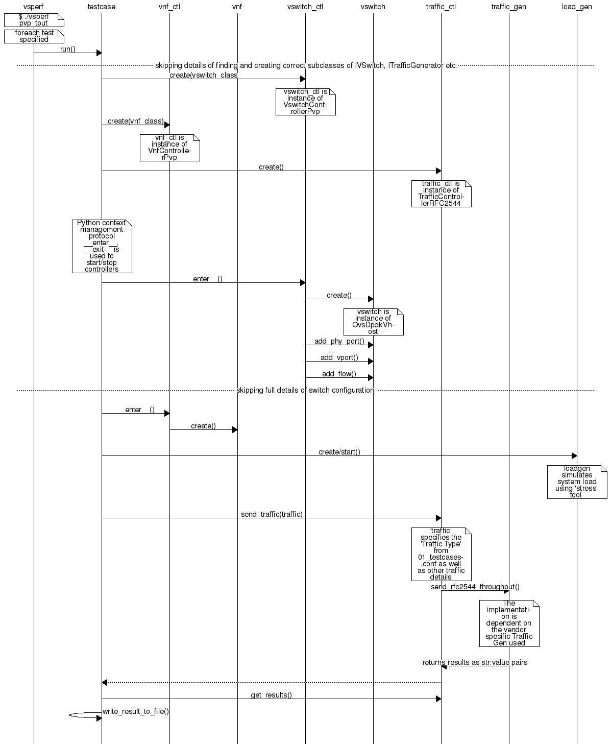
The controlled classes provide basic primitive operations. The Controllers sequence and co-ordinate these primitive operation in to useful actions. For instance the vswitch_controller_PVP can be used to bring any vSwitch (that implements the primitives defined in IVSwitch) into the configuration required by the Phy-to-Phy Deployment Scenario.
In order to support a new vSwitch only a new implementation of IVSwitch needs be created for the new vSwitch to be capable of fulfilling all the Deployment Scenarios provided for by existing or future vSwitch Controllers.
Similarly if a new Deployment Scenario is required it only needs to be written once as a new vSwitch Controller and it will immediately be capable of controlling all existing and future vSwitches in to that Deployment Scenario.
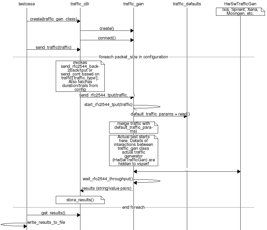
Similarly the Traffic Controllers can be used to co-ordinate basic operations provided by implementers of ITrafficGenerator to provide useful tests. Though traffic generators generally already implement full test cases i.e. they both generate suitable traffic and analyse returned traffic in order to implement a test which has typically been predefined in an RFC document. However the Traffic Controller class allows for the possibility of further enhancement - such as iterating over tests for various packet sizes or creating new tests.
3.1.5.6. Traffic Controller’s Role
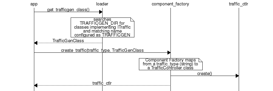
3.1.5.7. Loader & Component Factory
The working of the Loader package (which is responsible for finding arbitrary classes based on configuration data) and the Component Factory which is responsible for choosing the correct class for a particular situation - e.g. Deployment Scenario can be seen in this diagram.
3.1.6. Routing Tables
Vsperf uses a standard set of routing tables in order to allow tests to easily mix and match Deployment Scenarios (PVP, P2P topology), Tuple Matching and Frame Modification requirements.
+--------------+
|              |
| Table 0      |  table#0 - Match table. Flows designed to force 5 & 10
|              |  tuple matches go here.
|              |
+--------------+
       |
       |
       v
+--------------+  table#1 - Routing table. Flow entries to forward
|              |  packets between ports goes here.
| Table 1      |  The chosen port is communicated to subsequent tables by
|              |  setting the metadata value to the egress port number.
|              |  Generally this table is set-up by by the
+--------------+  vSwitchController.
       |
       |
       v
+--------------+  table#2 - Frame modification table. Frame modification
|              |  flow rules are isolated in this table so that they can
| Table 2      |  be turned on or off without affecting the routing or
|              |  tuple-matching flow rules. This allows the frame
|              |  modification and tuple matching required by the tests
|              |  in the VSWITCH PERFORMANCE FOR TELCO NFV test
+--------------+  specification to be independent of the Deployment
       |          Scenario set up by the vSwitchController.
       |
       v
+--------------+
|              |
| Table 3      |  table#3 - Egress table. Egress packets on the ports
|              |  setup in Table 1.
+--------------+
3.2. Traffic Generator Integration Guide
3.2.1. Intended Audience
This document is intended to aid those who want to integrate new traffic generator into the vsperf code. It is expected, that reader has already read generic part of VSPERF Design Document.
Let us create a sample traffic generator called sample_tg, step by step.
3.2.2. Step 1 - create a directory
Implementation of trafficgens is located at tools/pkt_gen/ directory, where every implementation has its dedicated sub-directory. It is required to create a new directory for new traffic generator implementations.
E.g.
$ mkdir tools/pkt_gen/sample_tg
3.2.3. Step 2 - create a trafficgen module
Every trafficgen class must inherit from generic ITrafficGenerator interface class. VSPERF during its initialization scans content of pkt_gen directory for all python modules, that inherit from ITrafficGenerator. These modules are automatically added into the list of supported traffic generators.
Example:
Let us create a draft of tools/pkt_gen/sample_tg/sample_tg.py module.
from tools.pkt_gen import trafficgen

class SampleTG(trafficgen.ITrafficGenerator):
    """
    A sample traffic generator implementation
    """
    pass
VSPERF is immediately aware of the new class:
$ ./vsperf --list-trafficgen
Output should look like:
Classes derived from: ITrafficGenerator
======

* Ixia:             A wrapper around the IXIA traffic generator.

* IxNet:            A wrapper around IXIA IxNetwork applications.

* Dummy:            A dummy traffic generator whose data is generated by the user.

* SampleTG:         A sample traffic generator implementation

* TestCenter:       Spirent TestCenter
3.2.4. Step 3 - configuration
All configuration values, required for correct traffic generator function, are passed from VSPERF to the traffic generator in a dictionary. Default values shared among all traffic generators are defined in tools/pkt_gen/trafficgen/trafficgenhelper.py as TRAFFIC_DEFAULTS dictionary. Default values are loaded by ITrafficGenerator interface class automatically, so it is not needed to load them explicitly. In case that there are any traffic generator specific default values, then they should be set within class specific __init__ function.
VSPERF passes test specific configuration within traffic dictionary to every start and send function. So implementation of these functions must ensure, that default values are updated with the testcase specific values. Proper merge of values is assured by call of merge_spec function from trafficgenhelper module.
Example of merge_spec usage in tools/pkt_gen/sample_tg/sample_tg.py module:
from tools.pkt_gen.trafficgen.trafficgenhelper import merge_spec

def start_rfc2544_throughput(self, traffic=None, duration=30):
    self._params = {}
    self._params['traffic'] = self.traffic_defaults.copy()
    if traffic:
        self._params['traffic'] = trafficgen.merge_spec(
            self._params['traffic'], traffic)
3.2.5. Step 4 - generic functions
There are some generic functions, which every traffic generator should provide. Although these functions are mainly optional, at least empty implementation must be provided. This is required, so that developer is explicitly aware of these functions.
The connect function is called from the traffic generator controller from its __enter__ method. This function should assure proper connection initialization between DUT and traffic generator. In case, that such implementation is not needed, empty implementation is required.
The disconnect function should perform clean up of any connection specific actions called from the connect function.
Example in tools/pkt_gen/sample_tg/sample_tg.py module:
def connect(self):
    pass

def disconnect(self):
    pass
3.2.6. Step 5 - supported traffic types
Currently VSPERF supports three different types of tests for traffic generators, these are identified in vsperf through the traffic type, which include:
- RFC2544 throughput - Send fixed size packets at different rates, using
traffic configuration, until minimum rate at which no packet loss is detected is found. Methods with its implementation have suffix _rfc2544_throughput.
- RFC2544 back2back - Send fixed size packets at a fixed rate, using traffic
configuration, for specified time interval. Methods with its implementation have suffix _rfc2544_back2back.
- continuous flow - Send fixed size packets at given framerate, using traffic
configuration, for specified time interval. Methods with its implementation have suffix _cont_traffic.
In general, both synchronous and asynchronous interfaces must be implemented for each traffic type. Synchronous functions start with prefix send_. Asynchronous with prefixes start_ and wait_ in case of throughput and back2back and start_ and stop_ in case of continuous traffic type.
Example of synchronous interfaces:
def send_rfc2544_throughput(self, traffic=None, tests=1, duration=20,
                            lossrate=0.0):
def send_rfc2544_back2back(self, traffic=None, tests=1, duration=20,
                           lossrate=0.0):
def send_cont_traffic(self, traffic=None, duration=20):
Example of asynchronous interfaces:
def start_rfc2544_throughput(self, traffic=None, tests=1, duration=20,
                             lossrate=0.0):
def wait_rfc2544_throughput(self):

def start_rfc2544_back2back(self, traffic=None, tests=1, duration=20,
                            lossrate=0.0):
def wait_rfc2544_back2back(self):

def start_cont_traffic(self, traffic=None, duration=20):
def stop_cont_traffic(self):
Description of parameters used by send, start, wait and stop functions:
param traffic: A dictionary with detailed definition of traffic pattern. It contains following parameters to be implemented by traffic generator.
Note: Traffic dictionary has also virtual switch related parameters, which are not listed below.
Note: There are parameters specific to testing of tunnelling protocols, which are discussed in detail at integration tests userguide
- param traffic_type: One of the supported traffic types, e.g. rfc2544, continuous or back2back.
- param frame_rate: Defines desired percentage of frame rate used during continuous stream tests. It can be set by test parameter iLoad or by CLI parameter iload.
- param bidir: Specifies if generated traffic will be full-duplex (true) or half-duplex (false).
- param multistream: Defines number of flows simulated by traffic generator. Value 0 disables MultiStream feature.
- param stream_type: Stream Type defines ISO OSI network layer used for simulation of multiple streams. Supported values:
- L2 - iteration of destination MAC address
- L3 - iteration of destination IP address
- L4 - iteration of destination port of selected transport protocol
- param l2: A dictionary with data link layer details, e.g. srcmac, dstmac and framesize.
- param l3: A dictionary with network layer details, e.g. srcip, dstip and proto.
- param l3: A dictionary with transport layer details, e.g. srcport, dstport.
- param vlan: A dictionary with vlan specific parameters, e.g. priority, cfi, id and vlan on/off switch enabled.
param tests: Number of times the test is executed.
param duration: Duration of continuous test or per iteration duration in case of RFC2544 throughput or back2back traffic types.
param lossrate: Acceptable lossrate percentage.
3.2.7. Step 6 - passing back results
It is expected that methods send, wait and stop will return values measured by traffic generator within a dictionary. Dictionary keys are defined in ResultsConstants implemented in core/results/results_constants.py. Please check sections for RFC2544 Throughput & Continuous and for Back2Back. The same key names should be used by all traffic generator implementations.
4. VSPERF LEVEL TEST PLAN (LTP)
4.1. Introduction
The objective of the OPNFV project titled Characterize vSwitch Performance for Telco NFV Use Cases, is to evaluate the performance of virtual switches to identify its suitability for a Telco Network Function Virtualization (NFV) environment. The intention of this Level Test Plan (LTP) document is to specify the scope, approach, resources, and schedule of the virtual switch performance benchmarking activities in OPNFV. The test cases will be identified in a separate document called the Level Test Design (LTD) document.
This document is currently in draft form.
4.1.1. Document identifier
The document id will be used to uniquely identify versions of the LTP. The format for the document id will be: OPNFV_vswitchperf_LTP_REL_STATUS, where by the status is one of: draft, reviewed, corrected or final. The document id for this version of the LTP is: OPNFV_vswitchperf_LTP_Colorado_REVIEWED.
4.1.2. Scope
The main purpose of this project is to specify a suite of performance tests in order to objectively measure the current packet transfer characteristics of a virtual switch in the NFVI. The intent of the project is to facilitate the performance testing of any virtual switch. Thus, a generic suite of tests shall be developed, with no hard dependencies to a single implementation. In addition, the test case suite shall be architecture independent.
The test cases developed in this project shall not form part of a separate test framework, all of these tests may be inserted into the Continuous Integration Test Framework and/or the Platform Functionality Test Framework - if a vSwitch becomes a standard component of an OPNFV release.
4.1.3. References
- RFC 1242 Benchmarking Terminology for Network Interconnection Devices
- RFC 2544 Benchmarking Methodology for Network Interconnect Devices
- RFC 2285 Benchmarking Terminology for LAN Switching Devices
- RFC 2889 Benchmarking Methodology for LAN Switching Devices
- RFC 3918 Methodology for IP Multicast Benchmarking
- RFC 4737 Packet Reordering Metrics
- RFC 5481 Packet Delay Variation Applicability Statement
- RFC 6201 Device Reset Characterization
4.1.4. Level in the overall sequence
The level of testing conducted by vswitchperf in the overall testing sequence (among all the testing projects in OPNFV) is the performance benchmarking of a specific component (the vswitch) in the OPNFV platfrom. It’s expected that this testing will follow on from the functional and integration testing conducted by other testing projects in OPNFV, namely Functest and Yardstick.
4.1.5. Test classes and overall test conditions
A benchmark is defined by the IETF as: A standardized test that serves as a basis for performance evaluation and comparison. It’s important to note that benchmarks are not Functional tests. They do not provide PASS/FAIL criteria, and most importantly ARE NOT performed on live networks, or performed with live network traffic.
In order to determine the packet transfer characteristics of a virtual switch, the benchmarking tests will be broken down into the following categories:
- Throughput Tests to measure the maximum forwarding rate (in frames per second or fps) and bit rate (in Mbps) for a constant load (as defined by RFC1242) without traffic loss.
- Packet and Frame Delay Tests to measure average, min and max packet and frame delay for constant loads.
- Stream Performance Tests (TCP, UDP) to measure bulk data transfer performance, i.e. how fast systems can send and receive data through the virtual switch.
- Request/Response Performance Tests (TCP, UDP) the measure the transaction rate through the virtual switch.
- Packet Delay Tests to understand latency distribution for different packet sizes and over an extended test run to uncover outliers.
- Scalability Tests to understand how the virtual switch performs as the number of flows, active ports, complexity of the forwarding logic’s configuration... it has to deal with increases.
- Control Path and Datapath Coupling Tests, to understand how closely coupled the datapath and the control path are as well as the effect of this coupling on the performance of the DUT.
- CPU and Memory Consumption Tests to understand the virtual
switch’s footprint on the system, this includes:
- CPU core utilization.
- CPU cache utilization.
- Memory footprint.
- System bus (QPI, PCI, ..) utilization.
- Memory lanes utilization.
- CPU cycles consumed per packet.
- Time To Establish Flows Tests.
- Noisy Neighbour Tests, to understand the effects of resource sharing on the performance of a virtual switch.
Note: some of the tests above can be conducted simultaneously where the combined results would be insightful, for example Packet/Frame Delay and Scalability.
4.2. Details of the Level Test Plan
This section describes the following items: * Test items and their identifiers (TestItems) * Test Traceability Matrix (TestMatrix) * Features to be tested (FeaturesToBeTested) * Features not to be tested (FeaturesNotToBeTested) * Approach (Approach) * Item pass/fail criteria (PassFailCriteria) * Suspension criteria and resumption requirements (SuspensionResumptionReqs)
4.2.1. Test items and their identifiers
The test item/application vsperf is trying to test are virtual switches and in particular their performance in an nfv environment. vsperf will first try to measure the maximum achievable performance by a virtual switch and then it will focus in on usecases that are as close to real life deployment scenarios as possible.
4.2.2. Test Traceability Matrix
vswitchperf leverages the “3x3” matrix (introduced in https://tools.ietf.org/html/draft-ietf-bmwg-virtual-net-02) to achieve test traceability. The matrix was expanded to 3x4 to accommodate scale metrics when displaying the coverage of many metrics/benchmarks). Test case covreage in the LTD is tracked using the following catagories:
| SPEED | ACCURACY | RELIABILITY | SCALE | |
| Activation | X | X | X | X |
| Operation | X | X | X | X |
| De-activation |
X = denotes a test catagory that has 1 or more test cases defined.
4.2.3. Features to be tested
Characterizing virtual switches (i.e. Device Under Test (DUT) in this document) includes measuring the following performance metrics:
- Throughput as defined by RFC1242: The maximum rate at which none of the offered frames are dropped by the DUT. The maximum frame rate and bit rate that can be transmitted by the DUT without any error should be recorded. Note there is an equivalent bit rate and a specific layer at which the payloads contribute to the bits. Errors and improperly formed frames or packets are dropped.
- Packet delay introduced by the DUT and its cumulative effect on E2E networks. Frame delay can be measured equivalently.
- Packet delay variation: measured from the perspective of the VNF/application. Packet delay variation is sometimes called “jitter”. However, we will avoid the term “jitter” as the term holds different meaning to different groups of people. In this document we will simply use the term packet delay variation. The preferred form for this metric is the PDV form of delay variation defined in RFC5481. The most relevant measurement of PDV considers the delay variation of a single user flow, as this will be relevant to the size of end-system buffers to compensate for delay variation. The measurement system’s ability to store the delays of individual packets in the flow of interest is a key factor that determines the specific measurement method. At the outset, it is ideal to view the complete PDV distribution. Systems that can capture and store packets and their delays have the freedom to calculate the reference minimum delay and to determine various quantiles of the PDV distribution accurately (in post-measurement processing routines). Systems without storage must apply algorithms to calculate delay and statistical measurements on the fly. For example, a system may store temporary estimates of the mimimum delay and the set of (100) packets with the longest delays during measurement (to calculate a high quantile, and update these sets with new values periodically. In some cases, a limited number of delay histogram bins will be available, and the bin limits will need to be set using results from repeated experiments. See section 8 of RFC5481.
- Packet loss (within a configured waiting time at the receiver): All packets sent to the DUT should be accounted for.
- Burst behaviour: measures the ability of the DUT to buffer packets.
- Packet re-ordering: measures the ability of the device under test to maintain sending order throughout transfer to the destination.
- Packet correctness: packets or Frames must be well-formed, in that they include all required fields, conform to length requirements, pass integrity checks, etc.
- Availability and capacity of the DUT i.e. when the DUT is fully “up”
and connected, following measurements should be captured for
DUT without any network packet load:
- Includes average power consumption of the CPUs (in various power states) and system over specified period of time. Time period should not be less than 60 seconds.
- Includes average per core CPU utilization over specified period of time. Time period should not be less than 60 seconds.
- Includes the number of NIC interfaces supported.
- Includes headroom of VM workload processing cores (i.e. available for applications).
4.2.4. Features not to be tested
vsperf doesn’t intend to define or perform any functional tests. The aim is to focus on performance.
4.2.5. Approach
The testing approach adoped by the vswitchperf project is black box testing, meaning the test inputs can be generated and the outputs captured and completely evaluated from the outside of the System Under Test. Some metrics can be collected on the SUT, such as cpu or memory utilization if the collection has no/minimal impact on benchmark. This section will look at the deployment scenarios and the general methodology used by vswitchperf. In addition, this section will also specify the details of the Test Report that must be collected for each of the test cases.
4.2.5.1. Deployment Scenarios
The following represents possible deployment test scenarios which can help to determine the performance of both the virtual switch and the datapaths to physical ports (to NICs) and to logical ports (to VNFs):
4.2.5.1.1. Physical port → vSwitch → physical port
                                                     _
+--------------------------------------------------+  |
|              +--------------------+              |  |
|              |                    |              |  |
|              |                    v              |  |  Host
|   +--------------+            +--------------+   |  |
|   |   phy port   |  vSwitch   |   phy port   |   |  |
+---+--------------+------------+--------------+---+ _|
           ^                           :
           |                           |
           :                           v
+--------------------------------------------------+
|                                                  |
|                traffic generator                 |
|                                                  |
+--------------------------------------------------+
4.2.5.1.2. Physical port → vSwitch → VNF → vSwitch → physical port
                                                      _
+---------------------------------------------------+  |
|                                                   |  |
|   +-------------------------------------------+   |  |
|   |                 Application               |   |  |
|   +-------------------------------------------+   |  |
|       ^                                  :        |  |
|       |                                  |        |  |  Guest
|       :                                  v        |  |
|   +---------------+           +---------------+   |  |
|   | logical port 0|           | logical port 1|   |  |
+---+---------------+-----------+---------------+---+ _|
        ^                                  :
        |                                  |
        :                                  v         _
+---+---------------+----------+---------------+---+  |
|   | logical port 0|          | logical port 1|   |  |
|   +---------------+          +---------------+   |  |
|       ^                                  :       |  |
|       |                                  |       |  |  Host
|       :                                  v       |  |
|   +--------------+            +--------------+   |  |
|   |   phy port   |  vSwitch   |   phy port   |   |  |
+---+--------------+------------+--------------+---+ _|
           ^                           :
           |                           |
           :                           v
+--------------------------------------------------+
|                                                  |
|                traffic generator                 |
|                                                  |
+--------------------------------------------------+
4.2.5.1.3. Physical port → vSwitch → VNF → vSwitch → VNF → vSwitch → physical port
                                                   _
+----------------------+  +----------------------+  |
|   Guest 1            |  |   Guest 2            |  |
|   +---------------+  |  |   +---------------+  |  |
|   |  Application  |  |  |   |  Application  |  |  |
|   +---------------+  |  |   +---------------+  |  |
|       ^       |      |  |       ^       |      |  |
|       |       v      |  |       |       v      |  |  Guests
|   +---------------+  |  |   +---------------+  |  |
|   | logical ports |  |  |   | logical ports |  |  |
|   |   0       1   |  |  |   |   0       1   |  |  |
+---+---------------+--+  +---+---------------+--+ _|
        ^       :                 ^       :
        |       |                 |       |
        :       v                 :       v        _
+---+---------------+---------+---------------+--+  |
|   |   0       1   |         |   3       4   |  |  |
|   | logical ports |         | logical ports |  |  |
|   +---------------+         +---------------+  |  |
|       ^       |                 ^       |      |  |  Host
|       |       L-----------------+       v      |  |
|   +--------------+          +--------------+   |  |
|   |   phy ports  | vSwitch  |   phy ports  |   |  |
+---+--------------+----------+--------------+---+ _|
        ^       ^                 :       :
        |       |                 |       |
        :       :                 v       v
+--------------------------------------------------+
|                                                  |
|                traffic generator                 |
|                                                  |
+--------------------------------------------------+
4.2.5.1.4. Physical port → VNF → vSwitch → VNF → physical port
                                                    _
+----------------------+  +----------------------+   |
|   Guest 1            |  |   Guest 2            |   |
|+-------------------+ |  | +-------------------+|   |
||     Application   | |  | |     Application   ||   |
|+-------------------+ |  | +-------------------+|   |
|       ^       |      |  |       ^       |      |   |  Guests
|       |       v      |  |       |       v      |   |
|+-------------------+ |  | +-------------------+|   |
||   logical ports   | |  | |   logical ports   ||   |
||  0              1 | |  | | 0              1  ||   |
++--------------------++  ++--------------------++  _|
    ^              :          ^              :
(PCI passthrough)  |          |     (PCI passthrough)
    |              v          :              |      _
+--------++------------+-+------------++---------+   |
|   |    ||        0   | |    1       ||     |   |   |
|   |    ||logical port| |logical port||     |   |   |
|   |    |+------------+ +------------+|     |   |   |
|   |    |     |                 ^     |     |   |   |
|   |    |     L-----------------+     |     |   |   |
|   |    |                             |     |   |   |  Host
|   |    |           vSwitch           |     |   |   |
|   |    +-----------------------------+     |   |   |
|   |                                        |   |   |
|   |                                        v   |   |
| +--------------+              +--------------+ |   |
| | phy port/VF  |              | phy port/VF  | |   |
+-+--------------+--------------+--------------+-+  _|
    ^                                        :
    |                                        |
    :                                        v
+--------------------------------------------------+
|                                                  |
|                traffic generator                 |
|                                                  |
+--------------------------------------------------+
4.2.5.1.5. Physical port → vSwitch → VNF
                                                      _
+---------------------------------------------------+  |
|                                                   |  |
|   +-------------------------------------------+   |  |
|   |                 Application               |   |  |
|   +-------------------------------------------+   |  |
|       ^                                           |  |
|       |                                           |  |  Guest
|       :                                           |  |
|   +---------------+                               |  |
|   | logical port 0|                               |  |
+---+---------------+-------------------------------+ _|
        ^
        |
        :                                            _
+---+---------------+------------------------------+  |
|   | logical port 0|                              |  |
|   +---------------+                              |  |
|       ^                                          |  |
|       |                                          |  |  Host
|       :                                          |  |
|   +--------------+                               |  |
|   |   phy port   |  vSwitch                      |  |
+---+--------------+------------ -------------- ---+ _|
           ^
           |
           :
+--------------------------------------------------+
|                                                  |
|                traffic generator                 |
|                                                  |
+--------------------------------------------------+
4.2.5.1.6. VNF → vSwitch → physical port
                                                      _
+---------------------------------------------------+  |
|                                                   |  |
|   +-------------------------------------------+   |  |
|   |                 Application               |   |  |
|   +-------------------------------------------+   |  |
|                                          :        |  |
|                                          |        |  |  Guest
|                                          v        |  |
|                               +---------------+   |  |
|                               | logical port  |   |  |
+-------------------------------+---------------+---+ _|
                                           :
                                           |
                                           v         _
+------------------------------+---------------+---+  |
|                              | logical port  |   |  |
|                              +---------------+   |  |
|                                          :       |  |
|                                          |       |  |  Host
|                                          v       |  |
|                               +--------------+   |  |
|                     vSwitch   |   phy port   |   |  |
+-------------------------------+--------------+---+ _|
                                       :
                                       |
                                       v
+--------------------------------------------------+
|                                                  |
|                traffic generator                 |
|                                                  |
+--------------------------------------------------+
4.2.5.1.7. VNF → vSwitch → VNF → vSwitch
                                                         _
+-------------------------+  +-------------------------+  |
|   Guest 1               |  |   Guest 2               |  |
|   +-----------------+   |  |   +-----------------+   |  |
|   |   Application   |   |  |   |   Application   |   |  |
|   +-----------------+   |  |   +-----------------+   |  |
|                :        |  |       ^                 |  |
|                |        |  |       |                 |  |  Guest
|                v        |  |       :                 |  |
|     +---------------+   |  |   +---------------+     |  |
|     | logical port 0|   |  |   | logical port 0|     |  |
+-----+---------------+---+  +---+---------------+-----+ _|
                :                    ^
                |                    |
                v                    :                    _
+----+---------------+------------+---------------+-----+  |
|    |     port 0    |            |     port 1    |     |  |
|    +---------------+            +---------------+     |  |
|              :                    ^                   |  |
|              |                    |                   |  |  Host
|              +--------------------+                   |  |
|                                                       |  |
|                     vswitch                           |  |
+-------------------------------------------------------+ _|
HOST 1(Physical port → virtual switch → VNF → virtual switch → Physical port) → HOST 2(Physical port → virtual switch → VNF → virtual switch → Physical port)
4.2.5.1.8. HOST 1 (PVP) → HOST 2 (PVP)
                                                   _
+----------------------+  +----------------------+  |
|   Guest 1            |  |   Guest 2            |  |
|   +---------------+  |  |   +---------------+  |  |
|   |  Application  |  |  |   |  Application  |  |  |
|   +---------------+  |  |   +---------------+  |  |
|       ^       |      |  |       ^       |      |  |
|       |       v      |  |       |       v      |  |  Guests
|   +---------------+  |  |   +---------------+  |  |
|   | logical ports |  |  |   | logical ports |  |  |
|   |   0       1   |  |  |   |   0       1   |  |  |
+---+---------------+--+  +---+---------------+--+ _|
        ^       :                 ^       :
        |       |                 |       |
        :       v                 :       v        _
+---+---------------+--+  +---+---------------+--+  |
|   |   0       1   |  |  |   |   3       4   |  |  |
|   | logical ports |  |  |   | logical ports |  |  |
|   +---------------+  |  |   +---------------+  |  |
|       ^       |      |  |       ^       |      |  |  Hosts
|       |       v      |  |       |       v      |  |
|   +--------------+   |  |   +--------------+   |  |
|   |   phy ports  |   |  |   |   phy ports  |   |  |
+---+--------------+---+  +---+--------------+---+ _|
        ^       :                 :       :
        |       +-----------------+       |
        :                                 v
+--------------------------------------------------+
|                                                  |
|                traffic generator                 |
|                                                  |
+--------------------------------------------------+
Note: For tests where the traffic generator and/or measurement receiver are implemented on VM and connected to the virtual switch through vNIC, the issues of shared resources and interactions between the measurement devices and the device under test must be considered.
Note: Some RFC 2889 tests require a full-mesh sending and receiving pattern involving more than two ports. This possibility is illustrated in the Physical port → vSwitch → VNF → vSwitch → VNF → vSwitch → physical port diagram above (with 2 sending and 2 receiving ports, though all ports could be used bi-directionally).
Note: When Deployment Scenarios are used in RFC 2889 address learning or cache capacity testing, an additional port from the vSwitch must be connected to the test device. This port is used to listen for flooded frames.
4.2.5.2. General Methodology:
To establish the baseline performance of the virtual switch, tests would initially be run with a simple workload in the VNF (the recommended simple workload VNF would be DPDK‘s testpmd application forwarding packets in a VM or vloop_vnf a simple kernel module that forwards traffic between two network interfaces inside the virtualized environment while bypassing the networking stack). Subsequently, the tests would also be executed with a real Telco workload running in the VNF, which would exercise the virtual switch in the context of higher level Telco NFV use cases, and prove that its underlying characteristics and behaviour can be measured and validated. Suitable real Telco workload VNFs are yet to be identified.
4.2.5.2.1. Default Test Parameters
The following list identifies the default parameters for suite of tests:
- Reference application: Simple forwarding or Open Source VNF.
- Frame size (bytes): 64, 128, 256, 512, 1024, 1280, 1518, 2K, 4k OR Packet size based on use-case (e.g. RTP 64B, 256B) OR Mix of packet sizes as maintained by the Functest project <https://wiki.opnfv.org/traffic_profile_management>.
- Reordering check: Tests should confirm that packets within a flow are not reordered.
- Duplex: Unidirectional / Bidirectional. Default: Full duplex with traffic transmitting in both directions, as network traffic generally does not flow in a single direction. By default the data rate of transmitted traffic should be the same in both directions, please note that asymmetric traffic (e.g. downlink-heavy) tests will be mentioned explicitly for the relevant test cases.
- Number of Flows: Default for non scalability tests is a single flow. For scalability tests the goal is to test with maximum supported flows but where possible will test up to 10 Million flows. Start with a single flow and scale up. By default flows should be added sequentially, tests that add flows simultaneously will explicitly call out their flow addition behaviour. Packets are generated across the flows uniformly with no burstiness. For multi-core tests should consider the number of packet flows based on vSwitch/VNF multi-thread implementation and behavior.
- Traffic Types: UDP, SCTP, RTP, GTP and UDP traffic.
- Deployment scenarios are:
- Physical → virtual switch → physical.
- Physical → virtual switch → VNF → virtual switch → physical.
- Physical → virtual switch → VNF → virtual switch → VNF → virtual switch → physical.
- Physical → VNF → virtual switch → VNF → physical.
- Physical → virtual switch → VNF.
- VNF → virtual switch → Physical.
- VNF → virtual switch → VNF.
Tests MUST have these parameters unless otherwise stated. Test cases with non default parameters will be stated explicitly.
Note: For throughput tests unless stated otherwise, test configurations should ensure that traffic traverses the installed flows through the virtual switch, i.e. flows are installed and have an appropriate time out that doesn’t expire before packet transmission starts.
4.2.5.2.2. Flow Classification
Virtual switches classify packets into flows by processing and matching particular header fields in the packet/frame and/or the input port where the packets/frames arrived. The vSwitch then carries out an action on the group of packets that match the classification parameters. Thus a flow is considered to be a sequence of packets that have a shared set of header field values or have arrived on the same port and have the same action applied to them. Performance results can vary based on the parameters the vSwitch uses to match for a flow. The recommended flow classification parameters for L3 vSwitch performance tests are: the input port, the source IP address, the destination IP address and the Ethernet protocol type field. It is essential to increase the flow time-out time on a vSwitch before conducting any performance tests that do not measure the flow set-up time. Normally the first packet of a particular flow will install the flow in the vSwitch which adds an additional latency, subsequent packets of the same flow are not subject to this latency if the flow is already installed on the vSwitch.
4.2.5.2.3. Test Priority
Tests will be assigned a priority in order to determine which tests should be implemented immediately and which tests implementations can be deferred.
Priority can be of following types: - Urgent: Must be implemented immediately. - High: Must be implemented in the next release. - Medium: May be implemented after the release. - Low: May or may not be implemented at all.
4.2.5.2.4. SUT Setup
The SUT should be configured to its “default” state. The SUT’s configuration or set-up must not change between tests in any way other than what is required to do the test. All supported protocols must be configured and enabled for each test set up.
4.2.5.2.5. Port Configuration
The DUT should be configured with n ports where n is a multiple of 2. Half of the ports on the DUT should be used as ingress ports and the other half of the ports on the DUT should be used as egress ports. Where a DUT has more than 2 ports, the ingress data streams should be set-up so that they transmit packets to the egress ports in sequence so that there is an even distribution of traffic across ports. For example, if a DUT has 4 ports 0(ingress), 1(ingress), 2(egress) and 3(egress), the traffic stream directed at port 0 should output a packet to port 2 followed by a packet to port 3. The traffic stream directed at port 1 should also output a packet to port 2 followed by a packet to port 3.
4.2.5.2.6. Frame Formats
Frame formats Layer 2 (data link layer) protocols
- Ethernet II
+---------------------------+-----------+
| Ethernet Header | Payload | Check Sum |
+-----------------+---------+-----------+
|_________________|_________|___________|
      14 Bytes     46 - 1500   4 Bytes
                     Bytes
Layer 3 (network layer) protocols
- IPv4
+-----------------+-----------+---------+-----------+
| Ethernet Header | IP Header | Payload | Checksum  |
+-----------------+-----------+---------+-----------+
|_________________|___________|_________|___________|
      14 Bytes       20 bytes  26 - 1480   4 Bytes
                                 Bytes
- IPv6
+-----------------+-----------+---------+-----------+
| Ethernet Header | IP Header | Payload | Checksum  |
+-----------------+-----------+---------+-----------+
|_________________|___________|_________|___________|
      14 Bytes       40 bytes  26 - 1460   4 Bytes
                                 Bytes
Layer 4 (transport layer) protocols
- TCP
- UDP
- SCTP
+-----------------+-----------+-----------------+---------+-----------+
| Ethernet Header | IP Header | Layer 4 Header  | Payload | Checksum  |
+-----------------+-----------+-----------------+---------+-----------+
|_________________|___________|_________________|_________|___________|
      14 Bytes      40 bytes      20 Bytes       6 - 1460   4 Bytes
                                                  Bytes
Layer 5 (application layer) protocols
- RTP
- GTP
+-----------------+-----------+-----------------+---------+-----------+
| Ethernet Header | IP Header | Layer 4 Header  | Payload | Checksum  |
+-----------------+-----------+-----------------+---------+-----------+
|_________________|___________|_________________|_________|___________|
      14 Bytes      20 bytes     20 Bytes        >= 6 Bytes   4 Bytes
4.2.5.2.7. Packet Throughput
There is a difference between an Ethernet frame, an IP packet, and a UDP datagram. In the seven-layer OSI model of computer networking, packet refers to a data unit at layer 3 (network layer). The correct term for a data unit at layer 2 (data link layer) is a frame, and at layer 4 (transport layer) is a segment or datagram.
Important concepts related to 10GbE performance are frame rate and throughput. The MAC bit rate of 10GbE, defined in the IEEE standard 802 .3ae, is 10 billion bits per second. Frame rate is based on the bit rate and frame format definitions. Throughput, defined in IETF RFC 1242, is the highest rate at which the system under test can forward the offered load, without loss.
The frame rate for 10GbE is determined by a formula that divides the 10 billion bits per second by the preamble + frame length + inter-frame gap.
The maximum frame rate is calculated using the minimum values of the following parameters, as described in the IEEE 802 .3ae standard:
- Preamble: 8 bytes * 8 = 64 bits
- Frame Length: 64 bytes (minimum) * 8 = 512 bits
- Inter-frame Gap: 12 bytes (minimum) * 8 = 96 bits
Therefore, Maximum Frame Rate (64B Frames) = MAC Transmit Bit Rate / (Preamble + Frame Length + Inter-frame Gap) = 10,000,000,000 / (64 + 512 + 96) = 10,000,000,000 / 672 = 14,880,952.38 frame per second (fps)
4.2.5.3. RFCs for testing virtual switch performance
The starting point for defining the suite of tests for benchmarking the performance of a virtual switch is to take existing RFCs and standards that were designed to test their physical counterparts and adapting them for testing virtual switches. The rationale behind this is to establish a fair comparison between the performance of virtual and physical switches. This section outlines the RFCs that are used by this specification.
4.2.5.3.1. RFC 1242 Benchmarking Terminology for Network Interconnection
Devices RFC 1242 defines the terminology that is used in describing performance benchmarking tests and their results. Definitions and discussions covered include: Back-to-back, bridge, bridge/router, constant load, data link frame size, frame loss rate, inter frame gap, latency, and many more.
4.2.5.3.2. RFC 2544 Benchmarking Methodology for Network Interconnect Devices
RFC 2544 outlines a benchmarking methodology for network Interconnect Devices. The methodology results in performance metrics such as latency, frame loss percentage, and maximum data throughput.
In this document network “throughput” (measured in millions of frames per second) is based on RFC 2544, unless otherwise noted. Frame size refers to Ethernet frames ranging from smallest frames of 64 bytes to largest frames of 9K bytes.
Types of tests are:
- Throughput test defines the maximum number of frames per second that can be transmitted without any error, or 0% loss ratio. In some Throughput tests (and those tests with long duration), evaluation of an additional frame loss ratio is suggested. The current ratio (10^-7 %) is based on understanding the typical user-to-user packet loss ratio needed for good application performance and recognizing that a single transfer through a vswitch must contribute a tiny fraction of user-to-user loss. Further, the ratio 10^-7 % also recognizes practical limitations when measuring loss ratio.
- Latency test measures the time required for a frame to travel from the originating device through the network to the destination device. Please note that RFC2544 Latency measurement will be superseded with a measurement of average latency over all successfully transferred packets or frames.
- Frame loss test measures the network’s response in overload conditions - a critical indicator of the network’s ability to support real-time applications in which a large amount of frame loss will rapidly degrade service quality.
- Burst test assesses the buffering capability of a virtual switch. It measures the maximum number of frames received at full line rate before a frame is lost. In carrier Ethernet networks, this measurement validates the excess information rate (EIR) as defined in many SLAs.
- System recovery to characterize speed of recovery from an overload condition.
- Reset to characterize speed of recovery from device or software reset. This type of test has been updated by RFC6201 as such, the methodology defined by this specification will be that of RFC 6201.
Although not included in the defined RFC 2544 standard, another crucial measurement in Ethernet networking is packet delay variation. The definition set out by this specification comes from RFC5481.
4.2.5.3.3. RFC 2285 Benchmarking Terminology for LAN Switching Devices
RFC 2285 defines the terminology that is used to describe the terminology for benchmarking a LAN switching device. It extends RFC 1242 and defines: DUTs, SUTs, Traffic orientation and distribution, bursts, loads, forwarding rates, etc.
4.2.5.3.4. RFC 2889 Benchmarking Methodology for LAN Switching
RFC 2889 outlines a benchmarking methodology for LAN switching, it extends RFC 2544. The outlined methodology gathers performance metrics for forwarding, congestion control, latency, address handling and finally filtering.
4.2.5.3.5. RFC 3918 Methodology for IP Multicast Benchmarking
RFC 3918 outlines a methodology for IP Multicast benchmarking.
4.2.5.3.6. RFC 4737 Packet Reordering Metrics
RFC 4737 describes metrics for identifying and counting re-ordered packets within a stream, and metrics to measure the extent each packet has been re-ordered.
4.2.5.3.7. RFC 5481 Packet Delay Variation Applicability Statement
RFC 5481 defined two common, but different forms of delay variation metrics, and compares the metrics over a range of networking circumstances and tasks. The most suitable form for vSwitch benchmarking is the “PDV” form.
4.2.5.3.8. RFC 6201 Device Reset Characterization
RFC 6201 extends the methodology for characterizing the speed of recovery of the DUT from device or software reset described in RFC 2544.
4.2.6. Item pass/fail criteria
vswitchperf does not specify Pass/Fail criteria for the tests in terms of a threshold, as benchmarks do not (and should not do this). The results/metrics for a test are simply reported. If it had to be defined, a test is considered to have passed if it succesfully completed and a relavent metric was recorded/reported for the SUT.
4.2.7. Suspension criteria and resumption requirements
In the case of a throughput test, a test should be suspended if a virtual switch is failing to forward any traffic. A test should be restarted from a clean state if the intention is to carry out the test again.
4.2.8. Test deliverables
Each test should produce a test report that details SUT information as well as the test results. There are a number of parameters related to the system, DUT and tests that can affect the repeatability of a test results and should be recorded. In order to minimise the variation in the results of a test, it is recommended that the test report includes the following information:
- Hardware details including:
- Platform details.
- Processor details.
- Memory information (see below)
- Number of enabled cores.
- Number of cores used for the test.
- Number of physical NICs, as well as their details (manufacturer, versions, type and the PCI slot they are plugged into).
- NIC interrupt configuration.
- BIOS version, release date and any configurations that were modified.
- Software details including:
- OS version (for host and VNF)
- Kernel version (for host and VNF)
- GRUB boot parameters (for host and VNF).
- Hypervisor details (Type and version).
- Selected vSwitch, version number or commit id used.
- vSwitch launch command line if it has been parameterised.
- Memory allocation to the vSwitch – which NUMA node it is using, and how many memory channels.
- Where the vswitch is built from source: compiler details including versions and the flags that were used to compile the vSwitch.
- DPDK or any other SW dependency version number or commit id used.
- Memory allocation to a VM - if it’s from Hugpages/elsewhere.
- VM storage type: snapshot/independent persistent/independent non-persistent.
- Number of VMs.
- Number of Virtual NICs (vNICs), versions, type and driver.
- Number of virtual CPUs and their core affinity on the host.
- Number vNIC interrupt configuration.
- Thread affinitization for the applications (including the vSwitch itself) on the host.
- Details of Resource isolation, such as CPUs designated for Host/Kernel (isolcpu) and CPUs designated for specific processes (taskset).
- Memory Details
- Total memory
- Type of memory
- Used memory
- Active memory
- Inactive memory
- Free memory
- Buffer memory
- Swap cache
- Total swap
- Used swap
- Free swap
- Test duration.
- Number of flows.
- Traffic Information:
- Traffic type - UDP, TCP, IMIX / Other.
- Packet Sizes.
- Deployment Scenario.
Note: Tests that require additional parameters to be recorded will explicitly specify this.
4.2.9. Test management
This section will detail the test activities that will be conducted by vsperf as well as the infrastructure that will be used to complete the tests in OPNFV.
4.2.10. Planned activities and tasks; test progression
A key consideration when conducting any sort of benchmark is trying to ensure the consistency and repeatability of test results between runs. When benchmarking the performance of a virtual switch there are many factors that can affect the consistency of results. This section describes these factors and the measures that can be taken to limit their effects. In addition, this section will outline some system tests to validate the platform and the VNF before conducting any vSwitch benchmarking tests.
System Isolation:
When conducting a benchmarking test on any SUT, it is essential to limit (and if reasonable, eliminate) any noise that may interfere with the accuracy of the metrics collected by the test. This noise may be introduced by other hardware or software (OS, other applications), and can result in significantly varying performance metrics being collected between consecutive runs of the same test. In the case of characterizing the performance of a virtual switch, there are a number of configuration parameters that can help increase the repeatability and stability of test results, including:
- OS/GRUB configuration:
- maxcpus = n where n >= 0; limits the kernel to using ‘n’ processors. Only use exactly what you need.
- isolcpus: Isolate CPUs from the general scheduler. Isolate all CPUs bar one which will be used by the OS.
- use taskset to affinitize the forwarding application and the VNFs onto isolated cores. VNFs and the vSwitch should be allocated their own cores, i.e. must not share the same cores. vCPUs for the VNF should be affinitized to individual cores also.
- Limit the amount of background applications that are running and set OS to boot to runlevel 3. Make sure to kill any unnecessary system processes/daemons.
- Only enable hardware that you need to use for your test – to ensure there are no other interrupts on the system.
- Configure NIC interrupts to only use the cores that are not allocated to any other process (VNF/vSwitch).
- NUMA configuration: Any unused sockets in a multi-socket system should be disabled.
- CPU pinning: The vSwitch and the VNF should each be affinitized to separate logical cores using a combination of maxcpus, isolcpus and taskset.
- BIOS configuration: BIOS should be configured for performance where an explicit option exists, sleep states should be disabled, any virtualization optimization technologies should be enabled, and hyperthreading should also be enabled, turbo boost and overclocking should be disabled.
System Validation:
System validation is broken down into two sub-categories: Platform validation and VNF validation. The validation test itself involves verifying the forwarding capability and stability for the sub-system under test. The rationale behind system validation is two fold. Firstly to give a tester confidence in the stability of the platform or VNF that is being tested; and secondly to provide base performance comparison points to understand the overhead introduced by the virtual switch.
Benchmark platform forwarding capability: This is an OPTIONAL test used to verify the platform and measure the base performance (maximum forwarding rate in fps and latency) that can be achieved by the platform without a vSwitch or a VNF. The following diagram outlines the set-up for benchmarking Platform forwarding capability:
                                                     __
+--------------------------------------------------+   |
|   +------------------------------------------+   |   |
|   |                                          |   |   |
|   |          l2fw or DPDK L2FWD app          |   |  Host
|   |                                          |   |   |
|   +------------------------------------------+   |   |
|   |                 NIC                      |   |   |
+---+------------------------------------------+---+ __|
           ^                           :
           |                           |
           :                           v
+--------------------------------------------------+
|                                                  |
|                traffic generator                 |
|                                                  |
+--------------------------------------------------+
Benchmark VNF forwarding capability: This test is used to verify the VNF and measure the base performance (maximum forwarding rate in fps and latency) that can be achieved by the VNF without a vSwitch. The performance metrics collected by this test will serve as a key comparison point for NIC passthrough technologies and vSwitches. VNF in this context refers to the hypervisor and the VM. The following diagram outlines the set-up for benchmarking VNF forwarding capability:
                                                     __
+--------------------------------------------------+   |
|   +------------------------------------------+   |   |
|   |                                          |   |   |
|   |                 VNF                      |   |   |
|   |                                          |   |   |
|   +------------------------------------------+   |   |
|   |          Passthrough/SR-IOV              |   |  Host
|   +------------------------------------------+   |   |
|   |                 NIC                      |   |   |
+---+------------------------------------------+---+ __|
           ^                           :
           |                           |
           :                           v
+--------------------------------------------------+
|                                                  |
|                traffic generator                 |
|                                                  |
+--------------------------------------------------+
Methodology to benchmark Platform/VNF forwarding capability
The recommended methodology for the platform/VNF validation and benchmark is: - Run RFC2889 Maximum Forwarding Rate test, this test will produce maximum forwarding rate and latency results that will serve as the expected values. These expected values can be used in subsequent steps or compared with in subsequent validation tests. - Transmit bidirectional traffic at line rate/max forwarding rate (whichever is higher) for at least 72 hours, measure throughput (fps) and latency. - Note: Traffic should be bidirectional. - Establish a baseline forwarding rate for what the platform can achieve. - Additional validation: After the test has completed for 72 hours run bidirectional traffic at the maximum forwarding rate once more to see if the system is still functional and measure throughput (fps) and latency. Compare the measure the new obtained values with the expected values.
NOTE 1: How the Platform is configured for its forwarding capability test (BIOS settings, GRUB configuration, runlevel...) is how the platform should be configured for every test after this
NOTE 2: How the VNF is configured for its forwarding capability test (# of vCPUs, vNICs, Memory, affinitization…) is how it should be configured for every test that uses a VNF after this.
Methodology to benchmark the VNF to vSwitch to VNF deployment scenario
vsperf has identified the following concerns when benchmarking the VNF to vSwitch to VNF deployment scenario:
- The accuracy of the timing synchronization between VNFs/VMs.
- The clock accuracy of a VNF/VM if they were to be used as traffic generators.
- VNF traffic generator/receiver may be using resources of the system under test, causing at least three forms of workload to increase as the traffic load increases (generation, switching, receiving).
The recommendation from vsperf is that tests for this sceanario must include an external HW traffic generator to act as the tester/traffic transmitter and receiver. The perscribed methodology to benchmark this deployment scanrio with an external tester involves the following three steps:
#. Determine the forwarding capability and latency through the virtual interface connected to the VNF/VM.
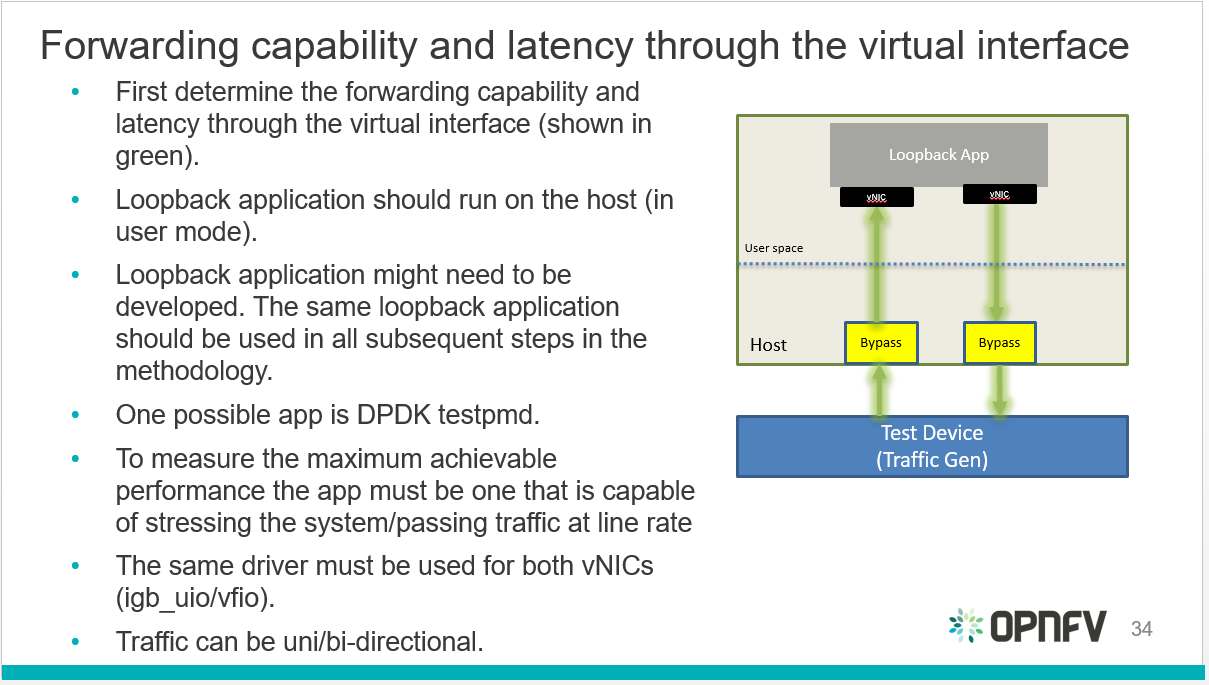
Virtual interfaces performance benchmark
- Determine the forwarding capability and latency through the VNF/hypervisor.
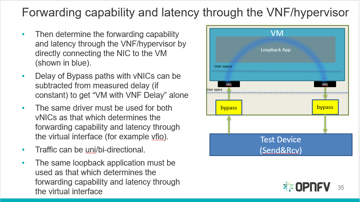
Hypervisor performance benchmark
- Determine the forwarding capability and latency for the VNF to vSwitch to VNF taking the information from the previous two steps into account.
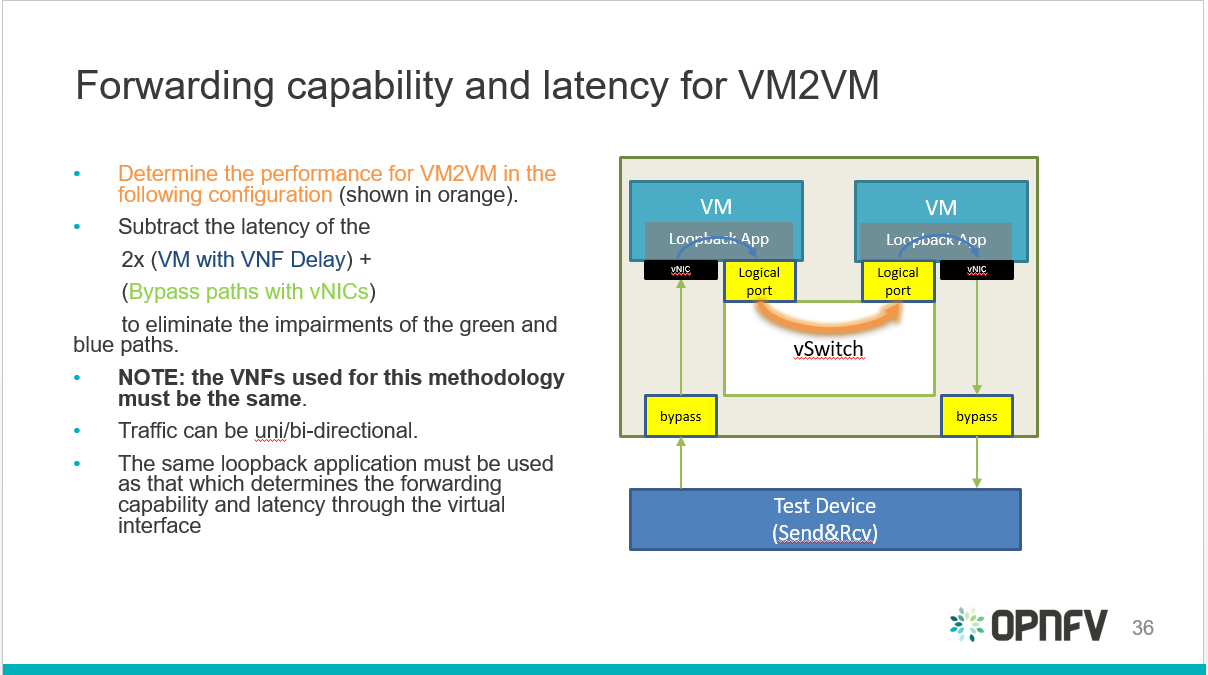
VNF to vSwitch to VNF performance benchmark
vsperf also identified an alternative configuration for the final step:
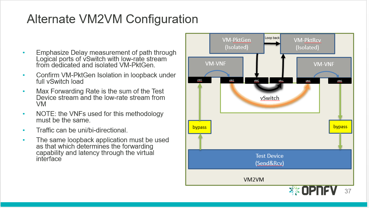
VNF to vSwitch to VNF alternative performance benchmark
4.2.11. Environment/infrastructure
Intel is providing a hosted test-bed with nine bare-metal environments allocated to different OPNFV projects. Currently a number of servers in Intel POD 3 are allocated to vsperf:
- pod3-wcp-node3 and pod3-wcp-node4 which are used for CI jobs.
- pod3-node6 which is used as a vsperf sandbox environment.
4.2.11.1. vsperf CI
vsperf CI jobs are broken down into:
Daily job: * Runs everyday takes about 10 hours to complete. * TESTCASES_DAILY=’phy2phy_tput back2back phy2phy_tput_mod_vlan
phy2phy_scalability pvp_tput pvp_back2back pvvp_tput pvvp_back2back’.
- TESTPARAM_DAILY=’–test-params pkt_sizes=64,128,512,1024,1518’.
Merge job: * Runs whenever patches are merged to master. * Runs a basic Sanity test.
Verify job: * Runs every time a patch is pushed to gerrit. * Builds documentation.
4.2.11.2. Scripts:
- There are 2 scripts that are part of VSPERFs CI:
- build-vsperf.sh: Lives in the VSPERF repository in the ci/ directory and is used to run vsperf with the appropriate cli parameters.
- vswitchperf.yml: YAML description of our jenkins job. lives in the RELENG repository.
More info on vsperf CI can be found here: https://wiki.opnfv.org/display/vsperf/VSPERF+CI
4.2.12. Responsibilities and authority
The group responsible for managing, designing, preparing and executing the tests listed in the LTD are the vsperf committers and contributors. The vsperf committers and contributors should work with the relavent OPNFV projects to ensure that the infrastructure is in place for testing vswitches, and that the results are published to common end point (a results database).
5. VSPERF LEVEL TEST DESIGN (LTD)
5.1. Introduction
The intention of this Level Test Design (LTD) document is to specify the set of tests to carry out in order to objectively measure the current characteristics of a virtual switch in the Network Function Virtualization Infrastructure (NFVI) as well as the test pass criteria. The detailed test cases will be defined in details-of-LTD, preceded by the doc-id and the scope.
This document is currently in draft form.
5.2. Document identifier
The document id will be used to uniquely identify versions of the LTD. The format for the document id will be: OPNFV_vswitchperf_LTD_REL_STATUS, where by the status is one of: draft, reviewed, corrected or final. The document id for this version of the LTD is: OPNFV_vswitchperf_LTD_Brahmaputra_REVIEWED.
5.3. Scope
The main purpose of this project is to specify a suite of performance tests in order to objectively measure the current packet transfer characteristics of a virtual switch in the NFVI. The intent of the project is to facilitate testing of any virtual switch. Thus, a generic suite of tests shall be developed, with no hard dependencies to a single implementation. In addition, the test case suite shall be architecture independent.
The test cases developed in this project shall not form part of a separate test framework, all of these tests may be inserted into the Continuous Integration Test Framework and/or the Platform Functionality Test Framework - if a vSwitch becomes a standard component of an OPNFV release.
5.4. References
- RFC 1242 Benchmarking Terminology for Network Interconnection Devices
- RFC 2544 Benchmarking Methodology for Network Interconnect Devices
- RFC 2285 Benchmarking Terminology for LAN Switching Devices
- RFC 2889 Benchmarking Methodology for LAN Switching Devices
- RFC 3918 Methodology for IP Multicast Benchmarking
- RFC 4737 Packet Reordering Metrics
- RFC 5481 Packet Delay Variation Applicability Statement
- RFC 6201 Device Reset Characterization
5.4.1. Details of the Level Test Design
This section describes the features to be tested (FeaturesToBeTested), and identifies the sets of test cases or scenarios (TestIdentification).
5.5. Features to be tested
Characterizing virtual switches (i.e. Device Under Test (DUT) in this document) includes measuring the following performance metrics:
- Throughput
- Packet delay
- Packet delay variation
- Packet loss
- Burst behaviour
- Packet re-ordering
- Packet correctness
- Availability and capacity of the DUT
5.6. Test identification
The following tests aim to determine the maximum forwarding rate that can be achieved with a virtual switch. The list is not exhaustive but should indicate the type of tests that should be required. It is expected that more will be added.
Title: RFC 2544 X% packet loss ratio Throughput and Latency Test
Prerequisite Test: N/A
Priority:
Description:
This test determines the DUT’s maximum forwarding rate with X% traffic loss for a constant load (fixed length frames at a fixed interval time). The default loss percentages to be tested are: - X = 0% - X = 10^-7%
Note: Other values can be tested if required by the user.
The selected frame sizes are those previously defined under Default Test Parameters. The test can also be used to determine the average latency of the traffic.
Under the RFC2544 test methodology, the test duration will include a number of trials; each trial should run for a minimum period of 60 seconds. A binary search methodology must be applied for each trial to obtain the final result.
Expected Result: At the end of each trial, the presence or absence of loss determines the modification of offered load for the next trial, converging on a maximum rate, or RFC2544 Throughput with X% loss. The Throughput load is re-used in related RFC2544 tests and other tests.
Metrics Collected:
The following are the metrics collected for this test:
- The maximum forwarding rate in Frames Per Second (FPS) and Mbps of the DUT for each frame size with X% packet loss.
- The average latency of the traffic flow when passing through the DUT (if testing for latency, note that this average is different from the test specified in Section 26.3 of RFC2544).
- CPU and memory utilization may also be collected as part of this test, to determine the vSwitch’s performance footprint on the system.
Title: RFC 2544 X% packet loss Throughput and Latency Test with packet modification
Prerequisite Test: N/A
Priority:
Description:
This test determines the DUT’s maximum forwarding rate with X% traffic loss for a constant load (fixed length frames at a fixed interval time). The default loss percentages to be tested are: - X = 0% - X = 10^-7%
Note: Other values can be tested if required by the user.
The selected frame sizes are those previously defined under Default Test Parameters. The test can also be used to determine the average latency of the traffic.
Under the RFC2544 test methodology, the test duration will include a number of trials; each trial should run for a minimum period of 60 seconds. A binary search methodology must be applied for each trial to obtain the final result.
During this test, the DUT must perform the following operations on the traffic flow:
- Perform packet parsing on the DUT’s ingress port.
- Perform any relevant address look-ups on the DUT’s ingress ports.
- Modify the packet header before forwarding the packet to the DUT’s egress port. Packet modifications include:
- Modifying the Ethernet source or destination MAC address.
- Modifying/adding a VLAN tag. (Recommended).
- Modifying/adding a MPLS tag.
- Modifying the source or destination ip address.
- Modifying the TOS/DSCP field.
- Modifying the source or destination ports for UDP/TCP/SCTP.
- Modifying the TTL.
Expected Result: The Packet parsing/modifications require some additional degree of processing resource, therefore the RFC2544 Throughput is expected to be somewhat lower than the Throughput level measured without additional steps. The reduction is expected to be greatest on tests with the smallest packet sizes (greatest header processing rates).
Metrics Collected:
The following are the metrics collected for this test:
- The maximum forwarding rate in Frames Per Second (FPS) and Mbps of the DUT for each frame size with X% packet loss and packet modification operations being performed by the DUT.
- The average latency of the traffic flow when passing through the DUT (if testing for latency, note that this average is different from the test specified in Section 26.3 of RFC2544).
- The RFC5481 PDV form of delay variation on the traffic flow, using the 99th percentile.
- CPU and memory utilization may also be collected as part of this test, to determine the vSwitch’s performance footprint on the system.
Title: RFC 2544 Throughput and Latency Profile
Prerequisite Test: N/A
Priority:
Description:
This test reveals how throughput and latency degrades as the offered rate varies in the region of the DUT’s maximum forwarding rate as determined by LTD.Throughput.RFC2544.PacketLossRatio (0% Packet Loss). For example it can be used to determine if the degradation of throughput and latency as the offered rate increases is slow and graceful or sudden and severe.
The selected frame sizes are those previously defined under Default Test Parameters.
The offered traffic rate is described as a percentage delta with respect to the DUT’s RFC 2544 Throughput as determined by LTD.Throughput.RFC2544.PacketLoss Ratio (0% Packet Loss case). A delta of 0% is equivalent to an offered traffic rate equal to the RFC 2544 Maximum Throughput; A delta of +50% indicates an offered rate half-way between the Maximum RFC2544 Throughput and line-rate, whereas a delta of -50% indicates an offered rate of half the RFC 2544 Maximum Throughput. Therefore the range of the delta figure is natuarlly bounded at -100% (zero offered traffic) and +100% (traffic offered at line rate).
The following deltas to the maximum forwarding rate should be applied:
- -50%, -10%, 0%, +10% & +50%
Expected Result: For each packet size a profile should be produced of how throughput and latency vary with offered rate.
Metrics Collected:
The following are the metrics collected for this test:
- The forwarding rate in Frames Per Second (FPS) and Mbps of the DUT for each delta to the maximum forwarding rate and for each frame size.
- The average latency for each delta to the maximum forwarding rate and for each frame size.
- CPU and memory utilization may also be collected as part of this test, to determine the vSwitch’s performance footprint on the system.
- Any failures experienced (for example if the vSwitch crashes, stops processing packets, restarts or becomes unresponsive to commands) when the offered load is above Maximum Throughput MUST be recorded and reported with the results.
Title: RFC 2544 System Recovery Time Test
Prerequisite Test LTD.Throughput.RFC2544.PacketLossRatio
Priority:
Description:
The aim of this test is to determine the length of time it takes the DUT to recover from an overload condition for a constant load (fixed length frames at a fixed interval time). The selected frame sizes are those previously defined under Default Test Parameters, traffic should be sent to the DUT under normal conditions. During the duration of the test and while the traffic flows are passing though the DUT, at least one situation leading to an overload condition for the DUT should occur. The time from the end of the overload condition to when the DUT returns to normal operations should be measured to determine recovery time. Prior to overloading the DUT, one should record the average latency for 10,000 packets forwarded through the DUT.
The overload condition SHOULD be to transmit traffic at a very high frame rate to the DUT (150% of the maximum 0% packet loss rate as determined by LTD.Throughput.RFC2544.PacketLossRatio or line-rate whichever is lower), for at least 60 seconds, then reduce the frame rate to 75% of the maximum 0% packet loss rate. A number of time-stamps should be recorded: - Record the time-stamp at which the frame rate was reduced and record a second time-stamp at the time of the last frame lost. The recovery time is the difference between the two timestamps. - Record the average latency for 10,000 frames after the last frame loss and continue to record average latency measurements for every 10,000 frames, when latency returns to within 10% of pre-overload levels record the time-stamp.
Expected Result:
Metrics collected
The following are the metrics collected for this test:
- The length of time it takes the DUT to recover from an overload condition.
- The length of time it takes the DUT to recover the average latency to pre-overload conditions.
Deployment scenario:
- Physical → virtual switch → physical.
Title: RFC2544 Back To Back Frames Test
Prerequisite Test: N
Priority:
Description:
The aim of this test is to characterize the ability of the DUT to process back-to-back frames. For each frame size previously defined under Default Test Parameters, a burst of traffic is sent to the DUT with the minimum inter-frame gap between each frame. If the number of received frames equals the number of frames that were transmitted, the burst size should be increased and traffic is sent to the DUT again. The value measured is the back-to-back value, that is the maximum burst size the DUT can handle without any frame loss. Please note a trial must run for a minimum of 2 seconds and should be repeated 50 times (at a minimum).
Expected Result:
Tests of back-to-back frames with physical devices have produced unstable results in some cases. All tests should be repeated in multiple test sessions and results stability should be examined.
Metrics collected
The following are the metrics collected for this test:
- The average back-to-back value across the trials, which is the number of frames in the longest burst that the DUT will handle without the loss of any frames.
- CPU and memory utilization may also be collected as part of this test, to determine the vSwitch’s performance footprint on the system.
Deployment scenario:
- Physical → virtual switch → physical.
Title: RFC 2889 X% packet loss Max Forwarding Rate Soak Test
Prerequisite Test LTD.Throughput.RFC2544.PacketLossRatio
Priority:
Description:
The aim of this test is to understand the Max Forwarding Rate stability over an extended test duration in order to uncover any outliers. To allow for an extended test duration, the test should ideally run for 24 hours or, if this is not possible, for at least 6 hours. For this test, each frame size must be sent at the highest Throughput rate with X% packet loss, as determined in the prerequisite test. The default loss percentages to be tested are: - X = 0% - X = 10^-7%
Note: Other values can be tested if required by the user.
Expected Result:
Metrics Collected:
The following are the metrics collected for this test:
- Max Forwarding Rate stability of the DUT.
- This means reporting the number of packets lost per time interval and reporting any time intervals with packet loss. The RFC2889 Forwarding Rate shall be measured in each interval. An interval of 60s is suggested.
- CPU and memory utilization may also be collected as part of this test, to determine the vSwitch’s performance footprint on the system.
- The RFC5481 PDV form of delay variation on the traffic flow, using the 99th percentile.
Title: RFC 2889 Max Forwarding Rate Soak Test with Frame Modification
Prerequisite Test: LTD.Throughput.RFC2544.PacketLossRatioFrameModification (0% Packet Loss)
Priority:
Description:
The aim of this test is to understand the Max Forwarding Rate stability over an extended test duration in order to uncover any outliers. To allow for an extended test duration, the test should ideally run for 24 hours or, if this is not possible, for at least 6 hour. For this test, each frame size must be sent at the highest Throughput rate with 0% packet loss, as determined in the prerequisite test.
During this test, the DUT must perform the following operations on the traffic flow:
- Perform packet parsing on the DUT’s ingress port.
- Perform any relevant address look-ups on the DUT’s ingress ports.
- Modify the packet header before forwarding the packet to the DUT’s egress port. Packet modifications include:
- Modifying the Ethernet source or destination MAC address.
- Modifying/adding a VLAN tag (Recommended).
- Modifying/adding a MPLS tag.
- Modifying the source or destination ip address.
- Modifying the TOS/DSCP field.
- Modifying the source or destination ports for UDP/TCP/SCTP.
- Modifying the TTL.
Expected Result:
Metrics Collected:
The following are the metrics collected for this test:
- Max Forwarding Rate stability of the DUT.
- This means reporting the number of packets lost per time interval and reporting any time intervals with packet loss. The RFC2889 Forwarding Rate shall be measured in each interval. An interval of 60s is suggested.
- CPU and memory utilization may also be collected as part of this test, to determine the vSwitch’s performance footprint on the system.
- The RFC5481 PDV form of delay variation on the traffic flow, using the 99th percentile.
Title: RFC 6201 Reset Time Test
Prerequisite Test: N/A
Priority:
Description:
The aim of this test is to determine the length of time it takes the DUT to recover from a reset.
Two reset methods are defined - planned and unplanned. A planned reset requires stopping and restarting the virtual switch by the usual ‘graceful’ method defined by it’s documentation. An unplanned reset requires simulating a fatal internal fault in the virtual switch - for example by using kill -SIGKILL on a Linux environment.
Both reset methods SHOULD be exercised.
For each frame size previously defined under Default Test Parameters, traffic should be sent to the DUT under normal conditions. During the duration of the test and while the traffic flows are passing through the DUT, the DUT should be reset and the Reset time measured. The Reset time is the total time that a device is determined to be out of operation and includes the time to perform the reset and the time to recover from it (cf. RFC6201).
RFC6201 defines two methods to measure the Reset time:
Frame-Loss Method: which requires the monitoring of the number of lost frames and calculates the Reset time based on the number of frames lost and the offered rate according to the following formula:
                   Frames_lost (packets)
Reset_time = -------------------------------------
               Offered_rate (packets per second)
Timestamp Method: which measures the time from which the last frame is forwarded from the DUT to the time the first frame is forwarded after the reset. This involves time-stamping all transmitted frames and recording the timestamp of the last frame that was received prior to the reset and also measuring the timestamp of the first frame that is received after the reset. The Reset time is the difference between these two timestamps.
According to RFC6201 the choice of method depends on the test tool’s capability; the Frame-Loss method SHOULD be used if the test tool supports:
- Counting the number of lost frames per stream.
- Transmitting test frame despite the physical link status.
- whereas the Timestamp method SHOULD be used if the test tool supports:
- Timestamping each frame.
- Monitoring received frame’s timestamp.
- Transmitting frames only if the physical link status is up.
Expected Result:
Metrics collected
The following are the metrics collected for this test:
- Average Reset Time over the number of trials performed.
Results of this test should include the following information:
- The reset method used.
- Throughput in Fps and Mbps.
- Average Frame Loss over the number of trials performed.
- Average Reset Time in milliseconds over the number of trials performed.
- Number of trials performed.
- Protocol: IPv4, IPv6, MPLS, etc.
- Frame Size in Octets
- Port Media: Ethernet, Gigabit Ethernet (GbE), etc.
- Port Speed: 10 Gbps, 40 Gbps etc.
- Interface Encapsulation: Ethernet, Ethernet VLAN, etc.
Deployment scenario:
- Physical → virtual switch → physical.
Title: RFC2889 Forwarding Rate Test
Prerequisite Test: LTD.Throughput.RFC2544.PacketLossRatio
Priority:
Description:
This test measures the DUT’s Max Forwarding Rate when the Offered Load is varied between the throughput and the Maximum Offered Load for fixed length frames at a fixed time interval. The selected frame sizes are those previously defined under Default Test Parameters. The throughput is the maximum offered load with 0% frame loss (measured by the prerequisite test), and the Maximum Offered Load (as defined by RFC2285) is “the highest number of frames per second that an external source can transmit to a DUT/SUT for forwarding to a specified output interface or interfaces”.
Traffic should be sent to the DUT at a particular rate (TX rate) starting with TX rate equal to the throughput rate. The rate of successfully received frames at the destination counted (in FPS). If the RX rate is equal to the TX rate, the TX rate should be increased by a fixed step size and the RX rate measured again until the Max Forwarding Rate is found.
The trial duration for each iteration should last for the period of time needed for the system to reach steady state for the frame size being tested. Under RFC2889 (Sec. 5.6.3.1) test methodology, the test duration should run for a minimum period of 30 seconds, regardless whether the system reaches steady state before the minimum duration ends.
Expected Result: According to RFC2889 The Max Forwarding Rate is the highest forwarding rate of a DUT taken from an iterative set of forwarding rate measurements. The iterative set of forwarding rate measurements are made by setting the intended load transmitted from an external source and measuring the offered load (i.e what the DUT is capable of forwarding). If the Throughput == the Maximum Offered Load, it follows that Max Forwarding Rate is equal to the Maximum Offered Load.
Metrics Collected:
The following are the metrics collected for this test:
- The Max Forwarding Rate for the DUT for each packet size.
- CPU and memory utilization may also be collected as part of this test, to determine the vSwitch’s performance footprint on the system.
Deployment scenario:
- Physical → virtual switch → physical. Note: Full mesh tests with multiple ingress and egress ports are a key aspect of RFC 2889 benchmarks, and scenarios with both 2 and 4 ports should be tested. In any case, the number of ports used must be reported.
Title: RFC2889 Forward Pressure Test
Prerequisite Test: LTD.Throughput.RFC2889.MaxForwardingRate
Priority:
Description:
The aim of this test is to determine if the DUT transmits frames with an inter-frame gap that is less than 12 bytes. This test overloads the DUT and measures the output for forward pressure. Traffic should be transmitted to the DUT with an inter-frame gap of 11 bytes, this will overload the DUT by 1 byte per frame. The forwarding rate of the DUT should be measured.
Expected Result: The forwarding rate should not exceed the maximum forwarding rate of the DUT collected by LTD.Throughput.RFC2889.MaxForwardingRate.
Metrics collected
The following are the metrics collected for this test:
- Forwarding rate of the DUT in FPS or Mbps.
- CPU and memory utilization may also be collected as part of this test, to determine the vSwitch’s performance footprint on the system.
Deployment scenario:
- Physical → virtual switch → physical.
Title: RFC2889 Error Frames Filtering Test
Prerequisite Test: N/A
Priority:
Description:
The aim of this test is to determine whether the DUT will propagate any erroneous frames it receives or whether it is capable of filtering out the erroneous frames. Traffic should be sent with erroneous frames included within the flow at random intervals. Illegal frames that must be tested include: - Oversize Frames. - Undersize Frames. - CRC Errored Frames. - Dribble Bit Errored Frames - Alignment Errored Frames
The traffic flow exiting the DUT should be recorded and checked to determine if the erroneous frames where passed through the DUT.
Expected Result: Broken frames are not passed!
Metrics collected
No Metrics are collected in this test, instead it determines:
- Whether the DUT will propagate erroneous frames.
- Or whether the DUT will correctly filter out any erroneous frames from traffic flow with out removing correct frames.
Deployment scenario:
- Physical → virtual switch → physical.
Title: RFC2889 Broadcast Frame Forwarding Test
Prerequisite Test: N
Priority:
Description:
The aim of this test is to determine the maximum forwarding rate of the DUT when forwarding broadcast traffic. For each frame previously defined under Default Test Parameters, the traffic should be set up as broadcast traffic. The traffic throughput of the DUT should be measured.
The test should be conducted with at least 4 physical ports on the DUT. The number of ports used MUST be recorded.
As broadcast involves forwarding a single incoming packet to several destinations, the latency of a single packet is defined as the average of the latencies for each of the broadcast destinations.
The incoming packet is transmitted on each of the other physical ports, it is not transmitted on the port on which it was received. The test MAY be conducted using different broadcasting ports to uncover any performance differences.
Expected Result:
Metrics collected:
The following are the metrics collected for this test:
- The forwarding rate of the DUT when forwarding broadcast traffic.
- The minimum, average & maximum packets latencies observed.
Deployment scenario:
- Physical → virtual switch 3x physical. In the Broadcast rate testing, four test ports are required. One of the ports is connected to the test device, so it can send broadcast frames and listen for miss-routed frames.
Title: Modified RFC 2544 X% packet loss ratio Throughput and Latency Test
Prerequisite Test: N/A
Priority:
Description:
This test determines the DUT’s maximum forwarding rate with X% traffic loss for a constant load (fixed length frames at a fixed interval time). The default loss percentages to be tested are: X = 0%, X = 10^-7%
Modified RFC 2544 throughput benchmarking methodology aims to quantify the throughput measurement variations observed during standard RFC 2544 benchmarking measurements of virtual switches and VNFs. The RFC2544 binary search algorithm is modified to use more samples per test trial to drive the binary search and yield statistically more meaningful results. This keeps the heart of the RFC2544 methodology, still relying on the binary search of throughput at specified loss tolerance, while providing more useful information about the range of results seen in testing. Instead of using a single traffic trial per iteration step, each traffic trial is repeated N times and the success/failure of the iteration step is based on these N traffic trials. Two types of revised tests are defined - Worst-of-N and Best-of-N.
Worst-of-N
Worst-of-N indicates the lowest expected maximum throughput for ( packet size, loss tolerance) when repeating the test.
- Repeat the same test run N times at a set packet rate, record each result.
- Take the WORST result (highest packet loss) out of N result samples, called the Worst-of-N sample.
- If Worst-of-N sample has loss less than the set loss tolerance, then the step is successful - increase the test traffic rate.
- If Worst-of-N sample has loss greater than the set loss tolerance then the step failed - decrease the test traffic rate.
- Go to step 1.
Best-of-N
Best-of-N indicates the highest expected maximum throughput for ( packet size, loss tolerance) when repeating the test.
- Repeat the same traffic run N times at a set packet rate, record each result.
- Take the BEST result (least packet loss) out of N result samples, called the Best-of-N sample.
- If Best-of-N sample has loss less than the set loss tolerance, then the step is successful - increase the test traffic rate.
- If Best-of-N sample has loss greater than the set loss tolerance, then the step failed - decrease the test traffic rate.
- Go to step 1.
Performing both Worst-of-N and Best-of-N benchmark tests yields lower and upper bounds of expected maximum throughput under the operating conditions, giving a very good indication to the user of the deterministic performance range for the tested setup.
Expected Result: At the end of each trial series, the presence or absence of loss determines the modification of offered load for the next trial series, converging on a maximum rate, or RFC2544 Throughput with X% loss. The Throughput load is re-used in related RFC2544 tests and other tests.
Metrics Collected:
The following are the metrics collected for this test:
- The maximum forwarding rate in Frames Per Second (FPS) and Mbps of the DUT for each frame size with X% packet loss.
- The average latency of the traffic flow when passing through the DUT (if testing for latency, note that this average is different from the test specified in Section 26.3 of RFC2544).
- Following may also be collected as part of this test, to determine the vSwitch’s performance footprint on the system:
- CPU core utilization.
- CPU cache utilization.
- Memory footprint.
- System bus (QPI, PCI, ...) utilization.
- CPU cycles consumed per packet.
Title: <tech> Overlay Network RFC 2544 X% packet loss ratio Throughput and Latency Test
NOTE: Throughout this test, four interchangeable overlay technologies are covered by the same test description. They are: VXLAN, GRE, NVGRE and GENEVE.
Prerequisite Test: N/A
Priority:
Description: This test evaluates standard switch performance benchmarks for the scenario where an Overlay Network is deployed for all paths through the vSwitch. Overlay Technologies covered (replacing <tech> in the test name) include:
- VXLAN
- GRE
- NVGRE
- GENEVE
Performance will be assessed for each of the following overlay network functions:
- Encapsulation only
- De-encapsulation only
- Both Encapsulation and De-encapsulation
For each native packet, the DUT must perform the following operations:
- Examine the packet and classify its correct overlay net (tunnel) assignment
- Encapsulate the packet
- Switch the packet to the correct port
For each encapsulated packet, the DUT must perform the following operations:
- Examine the packet and classify its correct native network assignment
- De-encapsulate the packet, if required
- Switch the packet to the correct port
The selected frame sizes are those previously defined under Default Test Parameters.
Thus, each test comprises an overlay technology, a network function, and a packet size with overlay network overhead included (but see also the discussion at https://etherpad.opnfv.org/p/vSwitchTestsDrafts ).
The test can also be used to determine the average latency of the traffic.
Under the RFC2544 test methodology, the test duration will include a number of trials; each trial should run for a minimum period of 60 seconds. A binary search methodology must be applied for each trial to obtain the final result for Throughput.
Expected Result: At the end of each trial, the presence or absence of loss determines the modification of offered load for the next trial, converging on a maximum rate, or RFC2544 Throughput with X% loss (where the value of X is typically equal to zero). The Throughput load is re-used in related RFC2544 tests and other tests.
Metrics Collected: The following are the metrics collected for this test:
- The maximum Throughput in Frames Per Second (FPS) and Mbps of the DUT for each frame size with X% packet loss.
- The average latency of the traffic flow when passing through the DUT and VNFs (if testing for latency, note that this average is different from the test specified in Section 26.3 of RFC2544).
- CPU and memory utilization may also be collected as part of this test, to determine the vSwitch’s performance footprint on the system.
Title: RFC 2544 X% packet loss ratio match action Throughput and Latency Test
Prerequisite Test: LTD.Throughput.RFC2544.PacketLossRatio
Priority:
Description:
The aim of this test is to determine the cost of carrying out match action(s) on the DUT’s RFC2544 Throughput with X% traffic loss for a constant load (fixed length frames at a fixed interval time).
- Each test case requires:
- selection of a specific match action(s),
- specifying a percentage of total traffic that is elligible for the match action,
- determination of the specific test configuration (number of flows, number of test ports, presence of an external controller, etc.), and
- measurement of the RFC 2544 Throughput level with X% packet loss: Traffic shall be bi-directional and symmetric.
Note: It would be ideal to verify that all match action-elligible traffic was forwarded to the correct port, and if forwarded to an unintended port it should be considered lost.
A match action is an action that is typically carried on a frame or packet that matches a set of flow classification parameters (typically frame/packet header fields). A match action may or may not modify a packet/frame. Match actions include [1]:
- output : outputs a packet to a particular port.
- normal: Subjects the packet to traditional L2/L3 processing (MAC learning).
- flood: Outputs the packet on all switch physical ports other than the port on which it was received and any ports on which flooding is disabled.
- all: Outputs the packet on all switch physical ports other than the port on which it was received.
- local: Outputs the packet on the ``local port,’’ which corresponds to the network device that has the same name as the bridge.
- in_port: Outputs the packet on the port from which it was received.
- Controller: Sends the packet and its metadata to the OpenFlow controller as a ``packet in’’ message.
- enqueue: Enqueues the packet on the specified queue within port.
- drop: discard the packet.
- Modifications include [1]:
- mod vlan: covered by LTD.Throughput.RFC2544.PacketLossRatioFrameModification
- mod_dl_src: Sets the source Ethernet address.
- mod_dl_dst: Sets the destination Ethernet address.
- mod_nw_src: Sets the IPv4 source address.
- mod_nw_dst: Sets the IPv4 destination address.
- mod_tp_src: Sets the TCP or UDP or SCTP source port.
- mod_tp_dst: Sets the TCP or UDP or SCTP destination port.
- mod_nw_tos: Sets the DSCP bits in the IPv4 ToS/DSCP or IPv6 traffic class field.
- mod_nw_ecn: Sets the ECN bits in the appropriate IPv4 or IPv6 field.
- mod_nw_ttl: Sets the IPv4 TTL or IPv6 hop limit field.
Note: This comprehensive list requires extensive traffic generator capabilities.
The match action(s) that were applied as part of the test should be reported in the final test report.
During this test, the DUT must perform the following operations on the traffic flow:
- Perform packet parsing on the DUT’s ingress port.
- Perform any relevant address look-ups on the DUT’s ingress ports.
- Carry out one or more of the match actions specified above.
The default loss percentages to be tested are: - X = 0% - X = 10^-7% Other values can be tested if required by the user. The selected frame sizes are those previously defined under Default Test Parameters.
The test can also be used to determine the average latency of the traffic when a match action is applied to packets in a flow. Under the RFC2544 test methodology, the test duration will include a number of trials; each trial should run for a minimum period of 60 seconds. A binary search methodology must be applied for each trial to obtain the final result.
Expected Result:
At the end of each trial, the presence or absence of loss determines the modification of offered load for the next trial, converging on a maximum rate, or RFC2544Throughput with X% loss. The Throughput load is re-used in related RFC2544 tests and other tests.
Metrics Collected:
- The following are the metrics collected for this test:
- The RFC 2544 Throughput in Frames Per Second (FPS) and Mbps of the DUT for each frame size with X% packet loss.
- The average latency of the traffic flow when passing through the DUT (if testing for latency, note that this average is different from the test specified in Section 26.3 ofRFC2544).
- CPU and memory utilization may also be collected as part of this test, to determine the vSwitch’s performance footprint on the system.
The metrics collected can be compared to that of the prerequisite test to determine the cost of the match action(s) in the pipeline.
Deployment scenario:
- Physical → virtual switch → physical (and others are possible)
- [1] ovs-ofctl - administer OpenFlow switches
- [http://openvswitch.org/support/dist-docs/ovs-ofctl.8.txt ]
These tests will measure the store and forward latency as well as the packet delay variation for various packet types through the virtual switch. The following list is not exhaustive but should indicate the type of tests that should be required. It is expected that more will be added.
Title: Initial Packet Processing Latency
Prerequisite Test: N/A
Priority:
Description:
In some virtual switch architectures, the first packets of a flow will take the system longer to process than subsequent packets in the flow. This test determines the latency for these packets. The test will measure the latency of the packets as they are processed by the flow-setup-path of the DUT. There are two methods for this test, a recommended method and a nalternative method that can be used if it is possible to disable the fastpath of the virtual switch.
Recommended method: This test will send 64,000 packets to the DUT, each belonging to a different flow. Average packet latency will be determined over the 64,000 packets.
Alternative method: This test will send a single packet to the DUT after a fixed interval of time. The time interval will be equivalent to the amount of time it takes for a flow to time out in the virtual switch plus 10%. Average packet latency will be determined over 1,000,000 packets.
This test is intended only for non-learning virtual switches; For learning virtual switches use RFC2889.
For this test, only unidirectional traffic is required.
Expected Result: The average latency for the initial packet of all flows should be greater than the latency of subsequent traffic.
Metrics Collected:
The following are the metrics collected for this test:
- Average latency of the initial packets of all flows that are processed by the DUT.
Deployment scenario:
- Physical → Virtual Switch → Physical.
Title: Packet Delay Variation Soak Test
Prerequisite Tests: LTD.Throughput.RFC2544.PacketLossRatio (0% Packet Loss)
Priority:
Description:
The aim of this test is to understand the distribution of packet delay variation for different frame sizes over an extended test duration and to determine if there are any outliers. To allow for an extended test duration, the test should ideally run for 24 hours or, if this is not possible, for at least 6 hour. For this test, each frame size must be sent at the highest possible throughput with 0% packet loss, as determined in the prerequisite test.
Expected Result:
Metrics Collected:
The following are the metrics collected for this test:
- The packet delay variation value for traffic passing through the DUT.
- The RFC5481 PDV form of delay variation on the traffic flow, using the 99th percentile, for each 60s interval during the test.
- CPU and memory utilization may also be collected as part of this test, to determine the vSwitch’s performance footprint on the system.
The general aim of these tests is to understand the impact of large flow table size and flow lookups on throughput. The following list is not exhaustive but should indicate the type of tests that should be required. It is expected that more will be added.
Title: RFC 2544 0% loss Flow Scalability throughput test
Prerequisite Test: LTD.Throughput.RFC2544.PacketLossRatio, IF the delta Throughput between the single-flow RFC2544 test and this test with a variable number of flows is desired.
Priority:
Description:
The aim of this test is to measure how throughput changes as the number of flows in the DUT increases. The test will measure the throughput through the fastpath, as such the flows need to be installed on the DUT before passing traffic.
For each frame size previously defined under Default Test Parameters and for each of the following number of flows:
- 1,000
- 2,000
- 4,000
- 8,000
- 16,000
- 32,000
- 64,000
- Max supported number of flows.
This test will be conducted under two conditions following the establishment of all flows as required by RFC 2544, regarding the flow expiration time-out:
- The time-out never expires during each trial.
2) The time-out expires for all flows periodically. This would require a short time-out compared with flow re-appearance for a small number of flows, and may not be possible for all flow conditions.
The maximum 0% packet loss Throughput should be determined in a manner identical to LTD.Throughput.RFC2544.PacketLossRatio.
Expected Result:
Metrics Collected:
The following are the metrics collected for this test:
- The maximum number of frames per second that can be forwarded at the specified number of flows and the specified frame size, with zero packet loss.
Title: RFC 2544 0% loss Memory Bandwidth Scalability test
Prerequisite Tests: LTD.Throughput.RFC2544.PacketLossRatio, IF the delta Throughput between an undisturbed RFC2544 test and this test with the Throughput affected by cache and memory bandwidth contention is desired.
Priority:
Description:
The aim of this test is to understand how the DUT’s performance is affected by cache sharing and memory bandwidth between processes.
During the test all cores not used by the vSwitch should be running a memory intensive application. This application should read and write random data to random addresses in unused physical memory. The random nature of the data and addresses is intended to consume cache, exercise main memory access (as opposed to cache) and exercise all memory buses equally. Furthermore:
- the ratio of reads to writes should be recorded. A ratio of 1:1 SHOULD be used.
- the reads and writes MUST be of cache-line size and be cache-line aligned.
- in NUMA architectures memory access SHOULD be local to the core’s node. Whether only local memory or a mix of local and remote memory is used MUST be recorded.
- the memory bandwidth (reads plus writes) used per-core MUST be recorded; the test MUST be run with a per-core memory bandwidth equal to half the maximum system memory bandwidth divided by the number of cores. The test MAY be run with other values for the per-core memory bandwidth.
- the test MAY also be run with the memory intensive application running on all cores.
Under these conditions the DUT’s 0% packet loss throughput is determined as per LTD.Throughput.RFC2544.PacketLossRatio.
Expected Result:
Metrics Collected:
The following are the metrics collected for this test:
- The DUT’s 0% packet loss throughput in the presence of cache sharing and memory bandwidth between processes.
- Title: VNF Scalability RFC 2544 X% packet loss ratio Throughput and
- Latency Test
Prerequisite Test: N/A
Priority:
Description:
This test determines the DUT’s throughput rate with X% traffic loss for a constant load (fixed length frames at a fixed interval time) when the number of VNFs on the DUT increases. The default loss percentages to be tested are: - X = 0% - X = 10^-7% . The minimum number of VNFs to be tested are 3.
Flow classification should be conducted with L2, L3 and L4 matching to understand the matching and scaling capability of the vSwitch. The matching fields which were used as part of the test should be reported as part of the benchmark report.
The vSwitch is responsible for forwarding frames between the VNFs
The SUT (vSwitch and VNF daisy chain) operation should be validated before running the test. This may be completed by running a burst or continuous stream of traffic through the SUT to ensure proper operation before a test.
Note: The traffic rate used to validate SUT operation should be low enough not to stress the SUT.
Note: Other values can be tested if required by the user.
Note: The same VNF should be used in the “daisy chain” formation. Each addition of a VNF should be conducted in a new test setup (The DUT is brought down, then the DUT is brought up again). An atlernative approach would be to continue to add VNFs without bringing down the DUT. The approach used needs to be documented as part of the test report.
The selected frame sizes are those previously defined under Default Test Parameters. The test can also be used to determine the average latency of the traffic.
Under the RFC2544 test methodology, the test duration will include a number of trials; each trial should run for a minimum period of 60 seconds. A binary search methodology must be applied for each trial to obtain the final result for Throughput.
Expected Result: At the end of each trial, the presence or absence of loss determines the modification of offered load for the next trial, converging on a maximum rate, or RFC2544 Throughput with X% loss. The Throughput load is re-used in related RFC2544 tests and other tests.
If the test VNFs are rather light-weight in terms of processing, the test provides a view of multiple passes through the vswitch on logical interfaces. In other words, the test produces an optimistic count of daisy-chained VNFs, but the cumulative effect of traffic on the vSwitch is “real” (assuming that the vSwitch has some dedicated resources, and the effects on shared resources is understood).
Metrics Collected: The following are the metrics collected for this test:
- The maximum Throughput in Frames Per Second (FPS) and Mbps of the DUT for each frame size with X% packet loss.
- The average latency of the traffic flow when passing through the DUT and VNFs (if testing for latency, note that this average is different from the test specified in Section 26.3 of RFC2544).
- CPU and memory utilization may also be collected as part of this test, to determine the vSwitch’s performance footprint on the system.
Title: VNF Scalability RFC 2544 Throughput and Latency Profile
Prerequisite Test: N/A
Priority:
Description:
This test reveals how throughput and latency degrades as the number of VNFs increases and offered rate varies in the region of the DUT’s maximum forwarding rate as determined by LTD.Throughput.RFC2544.PacketLossRatio (0% Packet Loss). For example it can be used to determine if the degradation of throughput and latency as the number of VNFs and offered rate increases is slow and graceful, or sudden and severe. The minimum number of VNFs to be tested is 3.
The selected frame sizes are those previously defined under Default Test Parameters.
The offered traffic rate is described as a percentage delta with respect to the DUT’s RFC 2544 Throughput as determined by LTD.Throughput.RFC2544.PacketLoss Ratio (0% Packet Loss case). A delta of 0% is equivalent to an offered traffic rate equal to the RFC 2544 Throughput; A delta of +50% indicates an offered rate half-way between the Throughput and line-rate, whereas a delta of -50% indicates an offered rate of half the maximum rate. Therefore the range of the delta figure is natuarlly bounded at -100% (zero offered traffic) and +100% (traffic offered at line rate).
The following deltas to the maximum forwarding rate should be applied:
- -50%, -10%, 0%, +10% & +50%
Note: Other values can be tested if required by the user.
Note: The same VNF should be used in the “daisy chain” formation. Each addition of a VNF should be conducted in a new test setup (The DUT is brought down, then the DUT is brought up again). An atlernative approach would be to continue to add VNFs without bringing down the DUT. The approach used needs to be documented as part of the test report.
Flow classification should be conducted with L2, L3 and L4 matching to understand the matching and scaling capability of the vSwitch. The matching fields which were used as part of the test should be reported as part of the benchmark report.
The SUT (vSwitch and VNF daisy chain) operation should be validated before running the test. This may be completed by running a burst or continuous stream of traffic through the SUT to ensure proper operation before a test.
Note: the traffic rate used to validate SUT operation should be low enough not to stress the SUT
Expected Result: For each packet size a profile should be produced of how throughput and latency vary with offered rate.
Metrics Collected:
The following are the metrics collected for this test:
- The forwarding rate in Frames Per Second (FPS) and Mbps of the DUT for each delta to the maximum forwarding rate and for each frame size.
- The average latency for each delta to the maximum forwarding rate and for each frame size.
- CPU and memory utilization may also be collected as part of this test, to determine the vSwitch’s performance footprint on the system.
- Any failures experienced (for example if the vSwitch crashes, stops processing packets, restarts or becomes unresponsive to commands) when the offered load is above Maximum Throughput MUST be recorded and reported with the results.
The general aim of these tests is to understand the capacity of the and speed with which the vswitch can accommodate new flows.
Title: RFC2889 Address Caching Capacity Test
Prerequisite Test: N/A
Priority:
Description:
Please note this test is only applicable to virtual switches that are capable of MAC learning. The aim of this test is to determine the address caching capacity of the DUT for a constant load (fixed length frames at a fixed interval time). The selected frame sizes are those previously defined under Default Test Parameters.
In order to run this test the aging time, that is the maximum time the DUT will keep a learned address in its flow table, and a set of initial addresses, whose value should be >= 1 and <= the max number supported by the implementation must be known. Please note that if the aging time is configurable it must be longer than the time necessary to produce frames from the external source at the specified rate. If the aging time is fixed the frame rate must be brought down to a value that the external source can produce in a time that is less than the aging time.
Learning Frames should be sent from an external source to the DUT to install a number of flows. The Learning Frames must have a fixed destination address and must vary the source address of the frames. The DUT should install flows in its flow table based on the varying source addresses. Frames should then be transmitted from an external source at a suitable frame rate to see if the DUT has properly learned all of the addresses. If there is no frame loss and no flooding, the number of addresses sent to the DUT should be increased and the test is repeated until the max number of cached addresses supported by the DUT determined.
Expected Result:
Metrics collected:
The following are the metrics collected for this test:
- Number of cached addresses supported by the DUT.
- CPU and memory utilization may also be collected as part of this test, to determine the vSwitch’s performance footprint on the system.
Deployment scenario:
- Physical → virtual switch → 2 x physical (one receiving, one listening).
Title: RFC2889 Address Learning Rate Test
Prerequisite Test: LTD.Memory.RFC2889.AddressCachingCapacity
Priority:
Description:
Please note this test is only applicable to virtual switches that are capable of MAC learning. The aim of this test is to determine the rate of address learning of the DUT for a constant load (fixed length frames at a fixed interval time). The selected frame sizes are those previously defined under Default Test Parameters, traffic should be sent with each IPv4/IPv6 address incremented by one. The rate at which the DUT learns a new address should be measured. The maximum caching capacity from LTD.Memory.RFC2889.AddressCachingCapacity should be taken into consideration as the maximum number of addresses for which the learning rate can be obtained.
Expected Result: It may be worthwhile to report the behaviour when operating beyond address capacity - some DUTs may be more friendly to new addresses than others.
Metrics collected:
The following are the metrics collected for this test:
- The address learning rate of the DUT.
Deployment scenario:
- Physical → virtual switch → 2 x physical (one receiving, one listening).
The following tests aim to determine how tightly coupled the datapath and the control path are within a virtual switch. The following list is not exhaustive but should indicate the type of tests that should be required. It is expected that more will be added.
Title: Control Path and Datapath Coupling
Prerequisite Test:
Priority:
Description:
The aim of this test is to understand how exercising the DUT’s control path affects datapath performance.
Initially a certain number of flow table entries are installed in the vSwitch. Then over the duration of an RFC2544 throughput test flow-entries are added and removed at the rates specified below. No traffic is ‘hitting’ these flow-entries, they are simply added and removed.
The test MUST be repeated with the following initial number of flow-entries installed: - < 10 - 1000 - 100,000 - 10,000,000 (or the maximum supported number of flow-entries)
The test MUST be repeated with the following rates of flow-entry addition and deletion per second: - 0 - 1 (i.e. 1 addition plus 1 deletion) - 100 - 10,000
Expected Result:
Metrics Collected:
The following are the metrics collected for this test:
- The maximum forwarding rate in Frames Per Second (FPS) and Mbps of the DUT.
- The average latency of the traffic flow when passing through the DUT (if testing for latency, note that this average is different from the test specified in Section 26.3 of RFC2544).
- CPU and memory utilization may also be collected as part of this test, to determine the vSwitch’s performance footprint on the system.
Deployment scenario:
- Physical → virtual switch → physical.
The following tests will profile a virtual switch’s CPU and memory utilization under various loads and circumstances. The following list is not exhaustive but should indicate the type of tests that should be required. It is expected that more will be added.
Title: RFC 2544 0% Loss CPU OR Memory Stress Test
Prerequisite Test:
Priority:
Description:
The aim of this test is to understand the overall performance of the system when a CPU or Memory intensive application is run on the same DUT as the Virtual Switch. For each frame size, an LTD.Throughput.RFC2544.PacketLossRatio (0% Packet Loss) test should be performed. Throughout the entire test a CPU or Memory intensive application should be run on all cores on the system not in use by the Virtual Switch. For NUMA system only cores on the same NUMA node are loaded.
It is recommended that stress-ng be used for loading the non-Virtual Switch cores but any stress tool MAY be used.
Expected Result:
Metrics Collected:
The following are the metrics collected for this test:
- Memory and CPU utilization of the cores running the Virtual Switch.
- The number of identity of the cores allocated to the Virtual Switch.
- The configuration of the stress tool (for example the command line parameters used to start it.)
- Note: Stress in the test ID can be replaced with the name of the
- component being stressed, when reporting the results: LTD.CPU.RFC2544.0PacketLoss or LTD.Memory.RFC2544.0PacketLoss
- Throughput tests
- Test ID: LTD.Throughput.RFC2544.PacketLossRatio
- Test ID: LTD.Throughput.RFC2544.PacketLossRatioFrameModification
- Test ID: LTD.Throughput.RFC2544.Profile
- Test ID: LTD.Throughput.RFC2544.SystemRecoveryTime
- Test ID: LTD.Throughput.RFC2544.BackToBackFrames
- Test ID: LTD.Throughput.RFC2889.Soak
- Test ID: LTD.Throughput.RFC2889.SoakFrameModification
- Test ID: LTD.Throughput.RFC6201.ResetTime
- Test ID: LTD.Throughput.RFC2889.MaxForwardingRate
- Test ID: LTD.Throughput.RFC2889.ForwardPressure
- Test ID: LTD.Throughput.RFC2889.ErrorFramesFiltering
- Test ID: LTD.Throughput.RFC2889.BroadcastFrameForwarding
- Test ID: LTD.Throughput.RFC2544.WorstN-BestN
- Test ID: LTD.Throughput.Overlay.Network.<tech>.RFC2544.PacketLossRatio
- Packet Latency tests
- Test ID: LTD.PacketLatency.InitialPacketProcessingLatency
- Test ID: LTD.PacketDelayVariation.RFC3393.Soak
- Scalability tests
- Test ID: LTD.Scalability.Flows.RFC2544.0PacketLoss
- Test ID: LTD.MemoryBandwidth.RFC2544.0PacketLoss.Scalability
- LTD.Scalability.VNF.RFC2544.PacketLossProfile
- LTD.Scalability.VNF.RFC2544.PacketLossRatio
- Acivation tests
- Test ID: LTD.Activation.RFC2889.AddressCachingCapacity
- Test ID: LTD.Activation.RFC2889.AddressLearningRate
- Coupling between control path and datapath Tests
- Test ID: LTD.CPDPCouplingFlowAddition
- CPU and memory consumption
- Test ID: LTD.Stress.RFC2544.0PacketLoss
6. VSPERF News
6.1. OPNFV Colorado Release
- Support for DPDK v16.07
- Support for yardstick testing framework
- Support for stp/rstp configuration
- Support for veth ports and network namespaces
- Support for multi-queue usage by testpmd loopback app
- Support for reporting of test execution length
- Support for MoonGen traffic generator.
- Support for OVS version 2.5 + DPDK 2.2.
- Support for DPDK v16.04
- Support for Xena traffic generator.
- Support for Red Hat Enterprise Linux
- Support for mode of operation (trafficgen, trafficgen-off)
- Support for Integration tests for OVS with DPDK including: * Physical ports. * Virtual ports (vhost user and vhost cuse). * Flow addition and removal tests. * Overlay (VXLAN, GRE and NVGRE) encapsulation and decapsulation tests.
- Supporting configuration of OVS with DPDK through the OVS DB as well as the legacy commandline arguments.
- Support for VM loopback (SR-IOV) benchmarking.
- Support for platform baseline benchmarking without a vswitch using testpmd.
- Support for Spirent Test Center REST APIs.
6.2. OPNFV Brahmaputra Release
Supports both OVS and OVS with DPDK.
Available tests:
- phy2phy_tput: LTD.Throughput.RFC2544.PacketLossRatio
- back2back: LTD.Throughput.RFC2544.BackToBackFrames
- phy2phy_tput_mod_vlan:LTD.Throughput.RFC2544.PacketLossRatioFrameModification
- phy2phy_cont: Phy2Phy Continuous Stream
- pvp_cont: PVP Continuous Stream
- pvvp_cont: PVVP Continuous Stream
- phy2phy_scalability:LTD.Scalability.RFC2544.0PacketLoss
- pvp_tput: LTD.Throughput.RFC2544.PacketLossRatio
- pvp_back2back: LTD.Throughput.RFC2544.BackToBackFrames
- pvvp_tput: LTD.Throughput.RFC2544.PacketLossRatio
- pvvp_back2back: LTD.Throughput.RFC2544.BackToBackFrames
- phy2phy_cpu_load: LTD.CPU.RFC2544.0PacketLoss
- phy2phy_mem_load: LTD.Memory.RFC2544.0PacketLoss
Supported deployment scenarios:
- Physical port -> vSwitch -> Physical port.
- Physical port -> vSwitch -> VNF -> vSwitch -> Physical port.
- Physical port -> vSwitch -> VNF -> vSwitch -> VNF -> vSwitch -> Physical port.
Loopback applications in the Guest can be:
- DPDK testpmd.
- Linux Bridge.
- l2fwd Kernel Module.
Supported traffic generators:
- Ixia: IxOS and IxNet.
- Spirent.
- Dummy.
6.2.1. Release Data
| Project | vswitchperf |
| Repo/tag | brahmaputra.1.0 |
| Release designation | Brahmaputra base release |
| Release date | February 26 2016 |
| Purpose of the delivery | Brahmaputra base release |
6.3. November 2015
- Support of opnfv_test_dashboard
6.4. October 2015
- Support of PVP and PVVP deployment scenarios using Vanilla OVS
6.5. September 2015
- Implementation of system statistics based upon pidstat command line tool.
- Support of PVVP deployment scenario using bhost-cuse and vhost user access methods
6.6. August 2015
- Backport and enhancement of reporting
- PVP deployment scenario testing using vhost-cuse as guest access method
- Implementation of LTD.Scalability.RFC2544.0PacketLoss testcase
- Support for background load generation with command line tools like stress and stress-ng
6.7. July 2015
- PVP deployment scenario testing using vhost-user as guest access method - Verified on CentOS7 and Fedora 20 - Requires QEMU 2.2.0 and DPDK 2.0
6.8. May 2015
This is the initial release of a re-designed version of the software based on community feedback. This initial release supports only the Phy2Phy deployment scenario and the LTD.Throughput.RFC2544.PacketLossRatio test - both described in the OPNFV vswitchperf ‘CHARACTERIZE VSWITCH PERFORMANCE FOR TELCO NFV USE CASES LEVEL TEST DESIGN’. The intention is that more test cases will follow once the community has digested the initial release.
- Performance testing with continuous stream
- Vanilla OVS support added.
- Support for non-DPDK OVS build.
- Build and installation support through Makefile will be added via next patch(Currently it is possible to manually build ovs and setting it in vsperf configuration files).
- PvP scenario is not yet implemented.
- CentOS7 support
- Verified on CentOS7
- Install & Quickstart documentation
- Better support for mixing tests types with Deployment Scenarios
- Re-work based on community feedback of TOIT
- Framework support for other vSwitches
- Framework support for non-Ixia traffic generators
- Framework support for different VNFs
- Python3
- Support for biDirectional functionality for ixnet interface
6.9. Missing
- xmlunit output is currently disabled
7. VSPERF Results
7.1. OPNFV Brahmaputra Scenarios
Available Tests and aspects of scenarios:
| Framework Test | Definition |
|---|---|
| phy2phy_tput | PacketLossRatio for Phy2Phy |
| back2back | BackToBackFrames for Phy2Phy |
| phy2phy_tput_mod_vlan | PacketLossRatioFrameModification for Phy2Phy |
| phy2phy_cont | Phy2Phy blast vswitch at x% TX rate and measure throughput |
| pvp_cont | PVP blast vswitch at x% TX rate and measure throughput |
| pvvp_cont | PVVP blast vswitch at x% TX rate and measure throughput |
| phy2phy_scalability | Scalability0PacketLoss for Phy2Phy |
| pvp_tput | PacketLossRatio for PVP |
| pvp_back2back | BackToBackFrames for PVP |
| pvvp_tput | PacketLossRatio for PVVP |
| pvvp_back2back | BackToBackFrames for PVVP |
| phy2phy_cpu_load | CPU0PacketLoss for Phy2Phy |
| phy2phy_mem_load | Same as CPU0PacketLoss but using a memory intensive app |
Supported deployment scenarios:
- Phy2Phy: Physical port -> vSwitch -> Physical port.
- PVP: Physical port -> vSwitch -> VNF -> vSwitch -> Physical port.
- PVVP: Physical port -> vSwitch -> VNF -> vSwitch -> VNF -> vSwitch -> Physical port.
Loopback applications in the Guest can be:
- DPDK testpmd.
- Linux Bridge.
- l2fwd.
Supported traffic generators:
- Ixia: IxOS and IxNet.
- Spirent.
- Dummy.
7.2. OPNFV Brahmaputra Results
The vsperf CI jobs that were used to obtain the results can be found at https://wiki.opnfv.org/wiki/vsperf_results.
The following table maps the results in the test dashboard to the appropriate test case in the VSPERF Framework and specifies the metric the vertical/Y axis is plotting. Please note, the presence of dpdk within a test name signifies that the vswitch under test was OVS with DPDK, while its absence indicates that the vswitch under test was stock OVS.
| Dashboard Test | Framework Test | Metric | Guest Interface |
|---|---|---|---|
| tput_ovsdpdk | phy2phy_tput | Throughput (FPS) | N/A |
| tput_ovs | phy2phy_tput | Throughput (FPS) | N/A |
| b2b_ovsdpdk | back2back | Back-to-back value | N/A |
| b2b_ovs | back2back | Back-to-back value | N/A |
| tput_mod_vlan_ovs | phy2phy_tput_mod_vlan | Throughput (FPS) | N/A |
| tput_mod_vlan_ovsdpdk | phy2phy_tput_mod_vlan | Throughput (FPS) | N/A |
| scalability_ovs | phy2phy_scalability | Throughput (FPS) | N/A |
| scalability_ovsdpdk | phy2phy_scalability | Throughput (FPS) | N/A |
| pvp_tput_ovsdpdkuser | pvp_tput | Throughput (FPS) | vhost-user |
| pvp_tput_ovsvirtio | pvp_tput | Throughput (FPS) | virtio-net |
| pvp_b2b_ovsdpdkuser | pvp_back2back | Back-to-back value | vhost-user |
| pvp_b2b_ovsvirtio | pvp_back2back | Back-to-back value | virtio-net |
| pvvp_tput_ovsdpdkuser | pvvp_tput | Throughput (FPS) | vhost-user |
| pvvp_tput_ovsvirtio | pvvp_tput | Throughput (FPS) | virtio-net |
| pvvp_b2b_ovsdpdkuser | pvvp_back2back | Throughput (FPS) | vhost-user |
| pvvp_b2b_ovsvirtio | pvvp_back2back | Throughput (FPS) | virtio-net |
The loopback application in the VNF used for PVP and PVVP scenarios was DPDK testpmd.