3. High Level Architecture
3.1. Introduction
The Anuket Kubernetes Reference Architecture (RA) is intended to be an industry standard independent Kubernetes reference architecture that is not tied to any specific offering or distribution. No vendor-specific enhancements are required in order to achieve conformance to the principles of Anuket specifications; conformance is achieved by using upstream components or features that are developed by the open source community. This allows operators to have a common Kubernetes-based architecture that supports any conformant VNF or CNF deployed on it to operate as expected. The purpose of this chapter is to outline all the components required to provide Kubernetes in a consistent and reliable way. The specification of how to use these components is detailed in Chapter 04.
Kubernetes is already a well documented and widely deployed Open Source project managed by the Cloud Native Computing Foundation (CNCF). Full documentation of the Kubernetes code and project can be found at https://kubernetes.io/docs/home/. The following chapters will only describe the specific features required by the Anuket Reference Architecture, and how they would be expected to be implemented. For any information related to standard Kubernetes features and capabilities, refer back to the standard Kubernetes documentation.
While this reference architecture provides options for pluggable components such as service mesh and other plugins that might be used, the focus of the reference architecture is on the abstracted interfaces and features that are required for telco type workload management and execution.
Chapter 5 of the Reference Model (RM) describes the hardware and software profiles that are descriptions of the capabilities and features that the Cloud Infrastructure provide to the workloads. As of v2.0, Figure 5-3 in the RM (also shown below) depicts a high level view of the software profile features that apply to each instance profile (Basic and High Performance). For more information on the instance profiles please refer to RM Chapter 4, section 4.2.4.
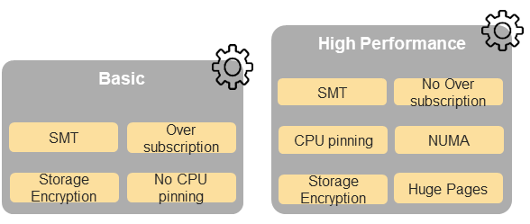
Figure 5-3 (from RM): NFVI softwareprofiles
In addition, the RM Figure 5-4 (shown below) depicts the hardware profile features that apply to each instance profile.
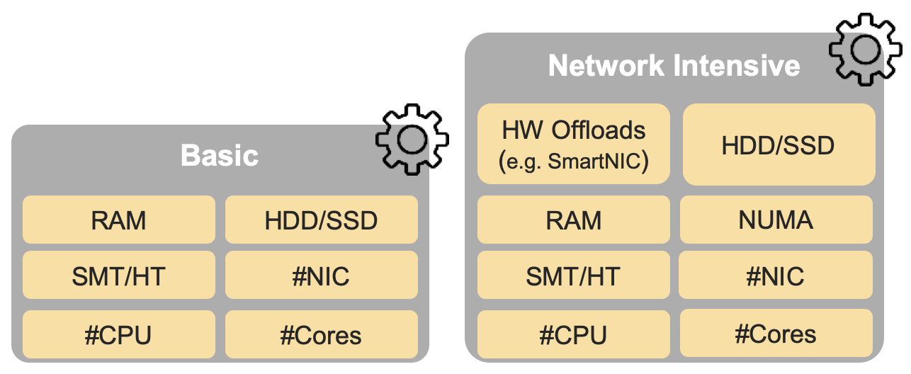
Figure 5-4 (from RM): NFVI hardwareprofiles and host associated capabilities
The features and capabilities described in the software and hardware profiles are considered throughout this RA, with the RA requirements traceability to the RM requirements formally documented in chapter 2, section 2.2 of this RA.
3.2. Infrastructure Services
3.2.1. Container Compute Services
The primary interface between the Physical / Virtual Infrastructure and any container-relevant components is the Kubernetes Node Operating System. This is the OS within which the container runtime exists, and within which the containers run (and therefore, the OS whose kernel is shared by the referenced containers). This is shown in Figure 3-1 below.
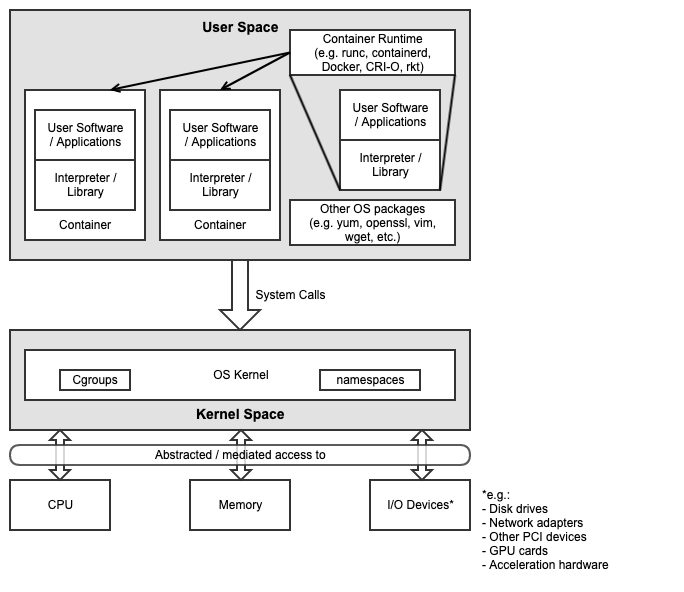
Figure 3-1: Kubernetes Node Operating System
The Kubernetes Node OS (as with any OS) consists of two main components:
Kernel space
User space
The Kernel is the tightly controlled space that provides an API to applications running in the user space (which usually have their own southbound interface in an interpreter or libraries). Key containerisation capabilities such as Control Groups (cgroups) and namespaces are kernel features, and are used and managed by the container runtime in order to provide isolation between the user space processes, which would also include the container itself as well as any processes running within it. The security of the Kubernetes Node OS and its relationship to the container and the applications running within the container or containers is essential to the overall security posture of the entire system, and must be appropriately secured to ensure processes running in one container cannot escalate their privileges or otherwise affect processes running in an adjacent container. An example and more details of this concept can be found in chapter 6.
It is important to note that the container runtime itself is also a set of processes that run in user space, and therefore also interact with the kernel via system calls. Many diagrams will show containers as running on top of the runtime, or inside the runtime. More accurately, the containers themselves are simply processes running within an OS, the container runtime is simply another set of processes that are used to manage these containers (pull, run, delete, etc.), and the kernel features required to provide the isolation mechanisms (cgroups, namespaces, filesystems, etc.) between the components.
3.2.1.1. Container Runtime Services
The Container Runtime is the component that runs within a Kubernetes Node Operating System (OS) and manages the underlying OS functionality, such as cgroups and namespaces (in Linux), in order to provide a service within which container images can be executed and make use of the infrastructure resources (compute, storage, networking and other I/O devices) abstracted by the Container Host OS, based on API instructions from the kubelet.
There are a number of different container runtimes. The simplest form, low-level container runtimes, just manage the OS capabilities such as cgroups and namespaces, and then run commands from within those cgroups and namespaces. An example of this type of runtime is runc, which underpins many of the higher-level runtimes and is considered a reference implementation of the Open Container Initiative (OCI) runtime spec. This specification includes details on how an implementation (i.e. an actual container runtime such as runc) must, for example, configure resource shares and limits (e.g. CPU, Memory, IOPS) for the containers that Kubernetes (via the kubelet) schedules on that host. This is important to ensure that the features and capabilities described in chapter 5 of the RM are supported by this RA and delivered by any downstream Reference Implementations (RIs) to the instance types defined in the RM.
Where low-level runtimes are used for the execution of a container within an OS, the more complex/complete high-level container runtimes are used for the general management of container images - moving them to where they need to be executed, unpacking them, and then passing them to the low-level runtime, which then executes the container. These high-level runtimes also include a comprehensive API that other applications (e.g. Kubernetes) can use to interact and manage the containers. An example of this type of runtime is containerd, which provides the features described above, before passing off the unpacked container image to runc for execution.
For Kubernetes the important interface to consider for container management is the Kubernetes Container Runtime Interface (CRI). This is an interface specification for any container runtime so that it is able to integrate with the kubelet on a Kubernetes Node. The CRI decouples the kubelet from the runtime that is running in the Host OS, meaning that the code required to integrate kubelet with a container runtime is not part of the kubelet itself (i.e. if a new container runtime is needed and it uses CRI, it will work with kubelet). Examples of this type of runtime include containerd (with CRI plugin) and cri-o, which is built specifically to work with Kubernetes.
To fulfil req.inf.vir.01 the architecture should support a container runtime
which provides the isolation of Operating System kernels.
The architecture must support a way to isolate the compute resources of the infrastructure itself from the workloads compute resources.
The basic semantics of Kubernetes, and the information found in manifests, defines the built-in Kubernetes objects and their desired state.
Kubernetes built in objects
Pod and workloads |
Description |
|---|---|
Pod is a collection of containers that can run on a node. This resource is created by clients and scheduled onto nodes. |
|
ReplicaSet ensures that a specified number of pod replicas are running at any given time. |
|
Deployment enables declarative updates for Pods and ReplicaSets. |
|
A Daemon set ensures that the correct nodes run a copy of a Pod. |
|
A Job represent a task, it creates one or more Pods and will continue to retry until the expected number of successful completions is reached. |
|
A CronJob manages time-based Jobs, namely: once at a specified point in time and repeatedly at a specified point in time. |
|
StatefulSet represents a set of pods with consistent identities. Identities are defined as: network, storage. |
3.2.1.2. CPU Management
CPU management has policies to determine placement preferences to use for workloads that are sensitive to cache affinity or latency, and so the workloads must not be moved by OS scheduler or throttled by kubelet. Additionally, some workloads are sensitive to differences between physical cores and SMT, while others (like DPDK-based workloads) are designed to run on isolated CPUs (like on Linux with cpuset-based selection of CPUs and isolcpus kernel parameter specifying cores isolated from general SMP balancing and scheduler algorithms).
Kubernetes CPU Manager works with Topology Manager. Special care needs to be taken of:
Supporting isolated CPUs: Using kubelet Reserved CPUs and Linux isolcpus allows configuration where only isolcpus are allocatable to pods. Scheduling pods to such nodes can be influenced with taints, tolerations and node affinity.
Differentiating between physical cores and SMT: When requesting even number of CPU cores for pods, scheduling can be influenced with taints, tolerations, and node affinity.
3.2.1.3. Memory and Huge Pages Resources Management
The Reference Model requires the support of huge pages in i.cap.018 which is supported by upstream Kubernetes (documentation).
For proper mapping of huge pages to scheduled pods, both need to have huge pages enabled in the operating system (configured in kernel and mounted with correct permissions) and kubelet configuration. Multiple sizes of huge pages can be enabled like 2 MiB and 1 GiB.
For some applications, huge pages should be allocated to account for consideration of the underlying HW topology. The Memory Manager (added to Kubernetes v1.21 as alpha feature) enables the feature of guaranteed memory and huge pages allocation for pods in the Guaranteed QoS class. The Memory Manager feeds the Topology Manager with hints for most suitable NUMA affinity.
3.2.1.4. Hardware Topology Management
Scheduling pods across NUMA boundaries can result in lower performance and higher latencies. This would be an issue for applications that require optimisations of CPU isolation, memory and device locality.
Kubernetes supports Topology policy per node as beta feature (documentation) and not per pod. The Topology Manager receives Topology information from Hint Providers which identify NUMA nodes (defined as server system architecture divisions of CPU sockets) and preferred scheduling. In the case of the pod with Guaranteed QoS class having integer CPU requests, the static CPU Manager policy would return topology hints relating to the exclusive CPU and the Device Manager would provide hints for the requested device.
If case that memory or huge pages are not considered by the Topology Manager, it can be done by the operating system providing best-effort local page allocation for containers as long as there is sufficient free local memory on the node, or with Control Groups (cgroups) cpuset subsystem that can isolate memory to single NUMA node.
3.2.1.5. Node Feature Discovery
Node Feature Discovery (NFD) can run on every node as a daemon or as a job. NFD detects detailed hardware and software capabilities of each node and then advertises those capabilities as node labels. Those node labels can be used in scheduling pods by using Node Selector or Node Affinity for pods that require such capabilities.
3.2.1.6. Device Plugin Framework
Device Plugin Framework advertises device hardware resources to kubelet with which vendors can implement plugins for devices that may require vendor-specific activation and life cycle management, and securely maps these devices to containers.
Figure 3-2 shows in four steps how device plugins operate on a Kubernetes node:
1: During setup, the cluster administrator (more in 3.2.5.1 Operator Pattern) knows or discovers (as per 3.2.1.5 Node Feature Discovery) what kind of devices are present on the different nodes, selects which devices to enable and deploys the associated device plugins.
2: The plugin reports the devices it found on the node to the Kubelet device manager and starts its gRPC server to monitor the devices.
3: A user submits a pod specification (workload manifest file) requesting a certain type of device.
4: The scheduler determines a suitable node based on device availability and the local kubelet assigns a specific device to the pod’s containers.
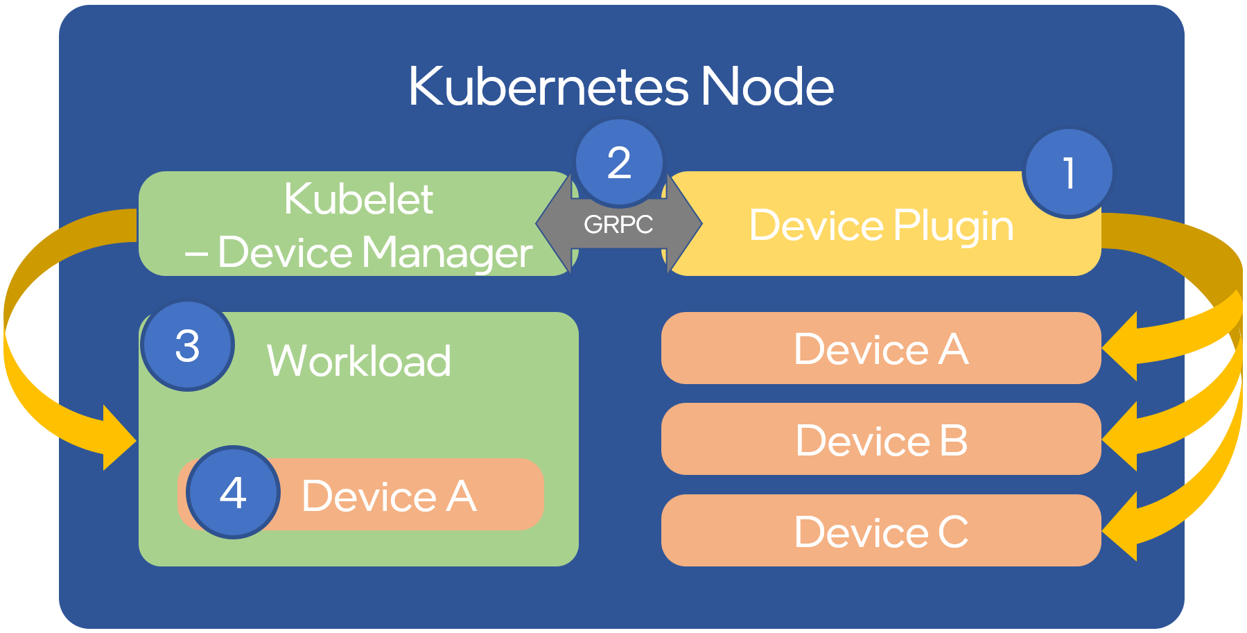
Figure 3-2: Device Plugin Operation
An example of often used device plugin is the SR-IOV Network Device Plugin, that discovers and advertises SR-IOV Virtual Functions (VFs) available on a Kubernetes node, and is used to map VFs to scheduled pods. To use it, the SR-IOV CNI is required, as well as a CNI multiplexer plugin (such as Multus CNI or DANM), to provision additional secondary network interfaces for VFs (beyond the primary network interface). The SR-IOV CNI during pod creation allocates a SR-IOV VF to a pod’s network namespace using the VF information given by the meta plugin, and on pod deletion releases the VF from the pod.
3.2.1.7. Hardware Acceleration
Hardware Acceleration Abstraction in RM 3.8 Hardware Acceleration Abstraction describes types of hardware acceleration (CPU instructions, Fixed function accelerators, Firmware-programmable adapters, SmartNICs and SmartSwitches), and usage for Infrastructure Level Acceleration and Application Level Acceleration.
Scheduling pods that require or prefer to run on nodes with hardware accelerators will depend on type of accelerator used:
CPU instructions can be found with Node Feature Discovery
Fixed function accelerators, Firmware-programmable network adapters and SmartNICs can be found and mapped to pods by using Device Plugin.
3.2.1.8. Scheduling Pods with Non-resilient Applications
Non-resilient applications are sensitive to platform impairments on Compute like pausing CPU cycles (for example because of OS scheduler) or Networking like packet drops, reordering or latencies. Such applications need to be carefully scheduled on nodes and preferably still decoupled from infrastructure details of those nodes.
# |
Intensive on |
Not intensive on |
Using hardware acceleration |
Requirements for optimised pod scheduling |
|---|---|---|---|---|
1 |
Compute |
Networking (dataplane) |
No |
CPU Manager |
2 |
Compute |
Networking (dataplane) |
CPU instructions |
CPU Manager, NFD |
3 |
Compute |
Networking (dataplane) |
Fixed function acceleration, Firmware-programmable network adapters or SmartNICs |
CPU Manager, Device Plugin |
4 |
Networking (dataplane) |
No, or Fixed function acceleration, Firmware- programmable network adapters or SmartNICs |
Huge pages (for DPDK-based applications); CPU Manager with configuration for isolcpus and SMT; Multiple interfaces; NUMA topology; Device Plugin |
|
5 |
Networking (dataplane) |
CPU instructions |
Huge pages (for DPDK-based applications); CPU Manager with configuration for isolcpus and SMT; Multiple interfaces; NUMA topology; Device Plugin; NFD |
Table 3-1: Categories of applications, requirements for scheduling pods and Kubernetes features
3.2.1.9. Virtual Machine based Clusters
Kubernetes clusters using above enhancements can implement worker nodes with “bare metal” servers (running Container Runtime in Linux host Operating System) or with virtual machines (VMs, on hypervisor).
When running in VMs, the following list of configurations shows what is needed for non-resilient applications:
CPU Manager managing vCPUs that hypervisor provides to VMs.
Huge pages enabled in hypervisor, mapped to VM, enabled in guest OS, and mapped to pod.
Hardware Topology Management with NUMA enabled in hypervisor, mapped into VM, if needed enabled in guest OS, and mapped into pod.
If Node Feature Discovery and Device Plugin Framework are required, the required CPU instructions must be enabled in the VM virtual hardware, and the required devices must be virtualised in the hypervisor or passed through to the Node VM, and mapped into the pods.
3.2.2. Container Networking Services
Kubernetes considers networking as a key component, with a number of distinct solutions. By default, Kubernetes networking is considered an “extension” to the core functionality, and is managed through the use of Network Plugins, which can be categorised based on the topology of the networks they manage, and the integration with the switching (e.g. vlan vs tunnels) and routing (e.g. virtual vs physical gateways) infrastructure outside of the Cluster:
Layer 2 underlay plugins provide east/west ethernet connectivity between pods and north/south connectivity between pods and external networks by using the network underlay (eg VLANs on DC switches). When using the underlay for layer 2 segments, configuration is required on the DC network for every network.
Layer 2 overlay plugins provide east/west pod-to-pod connectivity by creating overlay tunnels (eg VXLAN/GENEVE tunnels) between the nodes, without requiring creation of per-application layer 2 segments on the underlay. North-south connectivity cannot be provided.
Layer 3 plugins create a virtual router (eg BPF, iptables, kubeproxy) in each node, and can route traffic between multiple layer 2 overlays via them. North-south traffic is managed by peering (eg with BGP) virtual routers on the nodes with the DC network underlay, allowing each pod or service IP to be announced independently.
However, for more complex requirements such as providing connectivity through acceleration hardware, there are three approaches that can be taken, with Table 3-1 showing some of the differences between networking solutions that consist of these options. It is important to note that different networking solutions require different descriptors from the Kubernetes workloads (specifically, the deployment artefacts such as YAML files, etc.), therefore the networking solution should be agreed between the CNF vendors and the CNF operators:
The Default CNI Plugin through the use of deployment specific configuration (e.g. Tungsten Fabric)
A multiplexer/meta-plugin that integrates with the Kubernetes control plane via CNI (Container Network Interface) and allows for use of multiple CNI plugins in order to provide this specific connectivity that the default Network Plugin may not be able to provide (e.g. Multus, DANM)
An external, federated networking manager that uses the Kubernetes API Server to create and manage additional connections for Pods (e.g. Network Service Mesh)
Requirement |
Networking Solution with Multus |
Networking Solution with DANM |
Networking Solution with Tungsten Fabric |
Networking Solution with NSM |
|---|---|---|---|---|
Additional network connections provider |
Multiplexer/meta- plugin |
Multiplexer/meta- plugin |
Federated networking manager |
Default CNI Plugin |
The overlay network
encapsulation
protocol needs to
enable ECMP in the
underlay ( |
Supported via the additional CNI plugin |
Supported via the additional CNI plugin |
Supported |
TBC |
NAT ( |
Supported via the additional CNI plugin |
Supported |
Supported |
TBC |
Network Policies
(Security Groups)
( |
Supported via a CNI Network Plugin that supports Network Policies |
Supported via a CNI Network Plugin that supports Network Policies |
Supported via a CNI Network Plugin that supports Network Policies |
Supported via a CNI Network Plugin that supports Network Policies |
Traffic patterns
symmetry ( |
Depends on CNI plugin used |
Depends on CNI plugin used |
Depends on CNI plugin used |
Depends on CNI plugin used |
Centrally
administrated and
configured ( |
Supported via Kubernetes API Server |
Supported via Kubernetes API Server |
Supported via Kubernetes API Server |
Supported via Kubernetes API Server |
Dual stack IPv4 and
IPv6 for Kubernetes
workloads ( |
Supported via the additional CNI plugin |
Supported |
Supported |
Supported |
Integrating SDN
controllers ( |
Supported via the additional CNI plugin |
Supported via the additional CNI plugin |
TF is an SDN controller |
TBC |
More than one
networking solution
( |
Supported |
Supported |
Supported |
Supported |
Choose whether or
not to deploy more
than one networking
solution ( |
Supported |
Supported |
Supported |
Supported |
Kubernetes network
model ( |
Supported via the additional CNI plugin |
Supported via the additional CNI plugin |
Supported |
Supported via the default CNI plugin |
Do not interfere
with or cause
interference to any
interface or network
it does not own
( |
Supported |
Supported |
Supported |
Supported |
Cluster wide
coordination of IP
address assignment
( |
Supported via IPAM CNI plugin |
Supported |
Supported |
Supported via IPAM CNI plugin |
Table 3-1: Comparison of example networking solutions
For hardware resources that are needed by Kubernetes applications, Device Plugins can be used to manage those resources and advertise them to the kubelet for use by the Kubernetes applications. This allows resources such as “GPUs, high-performance NICs, FPGAs, InfiniBand adapters, and other similar computing resources that may require vendor specific initialisation and setup” to be managed and consumed via standard interfaces.
Figure 3-3 below shows the main building blocks of a Kubernetes networking solution:
Kubernetes Control Plane: this is the core of a Kubernetes Cluster - the apiserver, etcd cluster, kube-scheduler and the various controller-managers. The control plane (in particular the apiserver) provide a centralised point by which the networking solution is managed using a centralised management API.
Default CNI Plugin (Cluster Network): this is the default Cluster network plugin that has been deployed within the Cluster to provide IP addresses to Pods. Note that support for IPv6 requires not only changes in the Kubernetes control plane, but also requires the use of a CNI Plugin that support dual-stack networking.
CNI multiplexer/meta-plugin: as described above, this is an optional component that integrates with the Kubernetes control plane via CNI, but allows for the use of multiple CNI plugins and the provision of multiple network connections to each Pod, as shown by the use of additional CNI Plugin and
net0connection in the Pod. Note that the different network characteristics of the interfaces might require different networking technologies, which would potentially require different CNI plugins. Also note that this is only required for the High Performance profile. Example CNI implementations which meet these requirements include Multus and DANM.CNI Plugin (Additional): this is a CNI plugin that is used to provide additional networking needs to Pods, that aren’t provided by the default CNI plugin. This can include connectivity to underlay networks via accelerated hardware devices.
Device Plugin: this is a Kubernetes extension that allows for the management and advertisement of vendor hardware devices. In particular, devices such as FPGA, SR-IOV NICs, SmartNICs, etc. can be made available to Pods by using Device Plugins. Note that alignment of these devices, CPU topology and huge pages will need the use of the Topology Manager.
External / Application Load Balancing: As Kubernetes Ingress, Egress and Services have no support for all the protocols needed in telecommunication environments (Diameter, SIP, LDAP, etc) and their capacity is limited, the architecture includes the use of alternative load balancers, including external or ones built into the application. Management of external load balancers must be possible via Kubernetes API objects.
Other Features: these additional features that are required by the networking solution as a whole, may be delivered by the “Default CNI Plugin”, or the “CNI multiplexer/meta-plugin” if it is deployed. For example:
The integration of SDN solutions required by
req.inf.ntw.05is enabled via CNI integration.IP Address Management (IPAM) of the various networks can be provided by one or more IPAM plugins, which can be part of a CNI plugin, or some other component (i.e. external SDN solution) - it is key that there are no overlapping IP addresses within a Cluster, and if multiple IPAM solutions are used that they are co-ordinated in some way (as required by
req.inf.ntw.10).
Service Mesh: The well known service meshes are “application service meshes” that address and interact with the application layer 7 protocols (eg.: HTTP) only. Therefore, their support is not required in this architecture, as these service meshes are outside the scope of the infrastructure layer of this architecture.
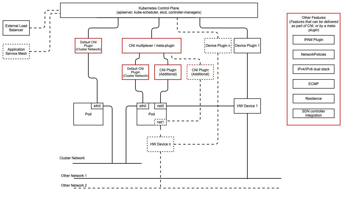
Figure 3-3: Kubernetes Networking Architecture
There are a number of different methods involved in managing, configuring and consuming networking resources in Kubernetes, including:
The Default Cluster Network can be installed and managed by config files, Kubernetes API Server (e.g. Custom Resource Definitions) or a combination of the two.
Additional networking management plane (e.g. CNI multiplexer/meta-plugin or federated networking manager) can be installed and managed by config files, Kubernetes API Server (e.g. Custom Resource Definitions) or a combination of the two.
The connecting of Pods to the Default Cluster Network is handled by the Default CNI Plugin (Cluster Network).
The connecting of Pods to the additional networks is handled by the additional networking management plane through the Kubernetes API (e.g. Custom Resource Definitions, Device Plugin API).
Configuration of these additional network connections to Pods (i.e. provision of an IP address to a Pod) can either be managed through the Kubernetes API (e.g. Custom Resource Definitions) or an external management plane (e.g. dynamic address assignment from a VPN server).
There are several types of low latency and high throughput networks required by
telco workloads: signalling traffic workloads and user plane traffic workloads.
Networks used for signalling traffic are more demanding than what a standard
overlay network can handle, but still do not need the use of user space
networking. Due to the nature of the signalling protocols used, these type of
networks require NAT-less communication documented in infra.net.cfg.003 and will
need to be served by a CNI plugin with IPVLAN or MACVLAN support. On the other
hand, the low latency, high throughput networks used for handling the user plane
traffic require the capability to use a user space networking technology.
Note: An infrastructure can provide the possibility to use SR-IOV with DPDK as an additional feature and still be conformant with Anuket.
3.2.3. Kubernetes Networking Semantics
The support for advanced network configuration management doesn’t exist in core Kubernetes. Kubernetes is missing the advanced networking configuration component of Infrastructure as a Service (IaaS). For example, there is no network configuration API, there is no way to create L2 networks, instantiate network services such as L3aaS and LBaaS and then connect them all together.
Kubernetes networking can be divided into two parts, built in network functionality available through the pod’s mandatory primary interface and network functionality available through the pod’s optional secondary interfaces.
3.2.3.1. Built-in Kubernetes Network Functionality
Kubernetes currently only allows for one network, the cluster network, and one network attachment for each pod. All pods and containers have an eth0 interface, this interface is created by Kubernetes at pod creation and attached to the cluster network. All communication to and from the pod is done through this interface. To only allow for one interface in a pod removes the need for traditional networking tools such as VRFs and additional routes and routing tables inside the pod network namespace.
The basic semantics of Kubernetes, and the information found in manifests, defines the connectivity rules and behavior without any references to IP addresses. This has many advantages, it makes it easy to create portable, scalable SW services and network policies for them that are not location aware and therefore can be executed more or less anywhere.
Network objects |
Description |
|---|---|
Ingress is a collection of rules that allow inbound connections to reach the endpoints defined by a backend. An Ingress can be configured to give services externally reachable URLs, load balance traffic, terminate SSL, offer name based virtual hosting etc. |
|
Service is a named abstraction of an application running on a set of pods consisting of a local port (for example 3306) that the proxy listens on, and the selector that determines which pods will answer requests sent through the proxy. |
|
Endpoints and Endpointslices are a collection of objects that contain the ip address, v4 and v6, of the pods that represents a service. |
|
Network Policy defines which network traffic is allowed to ingress and egress from a set of pods. |
There is no need to explicitly define internal load balancers, server pools, service monitors, firewalls and so on. The Kubernetes semantics and relation between the different objects defined in the object manifests contains all the information needed.
Example: The manifests for service my-service and the deployment with the four load balanced pods of type my-app
Service:
apiVersion: v1
kind: Service
metadata:
        name: my-service
        spec:
                selector:
                        app: my-app
                ports:
                        - protocol: TCP
                                port: 123
Deployment:
apiVersion: apps/v1
kind: Deployment
metadata: name: my-app-deployment
spec:
        selector:
                matchLabels:
                        app: my-app
                        replicas: 4
                        template:
                                metadata:
                                        labels:
                                                app: my-app
                        spec:
                                containers:
                                        - name: my-app
                                          image: my-app-1.2.3
                                          ports:
                                          - containerPort: 123
This is all that is needed to deploy 4 pods/containers that are fronted by a service that performes load balancing. The Deployment will ensure that there are always four pods of type my-app available. the Deployment is responsible for the full lifecycle management of the pods, this includes in service update/upgrade.
None of this is of much help however when implementing network service functions such as VNFs/CNFs that operate on multiple networks and require advanced networking configurations.
3.2.3.2. Multiple Networks and Advanced Configurations
Kubernetes does currently not in itself support multiple networks, pod multiple network attachments or advanced network configurations. This is supported by using a Container Network Interface multiplexer such as Multus. A considerable effort is being invested to add better network support to Kubernetes, all such activities are coordinated through the kubernetes Network Special Interest Group and it’s sub groups. One such group, the Network Plumbing Working Group has produced the Kubernetes Network Custom Resource Definition De-facto Standard. This document describes how secondary networks can be defined and attached to pods.
This defacto standard defines among other things
Definition |
Description |
|---|---|
Kubernetes Cluster-Wide default network |
A network to which all pods are attached following the current behavior and requirements of Kubernetes, this done by attaching the eth0 interface to the pod namespace. |
Network Attachment |
A means of allowing a pod to directly communicate with a given logical or physical network. Typically (but not necessarily) each attachment takes the form of a kernel network interface placed into the pod’s network namespace. Each attachment may result in zero or more IP addresses being assigned to the pod. |
NetworkAttachmentDefinition object |
This defines resource object that describes how to attach a pod to a logical or physical network, the annotation name is “k8s.v1.cni.cncf.io/networks” |
Network Attachment Selection Annotation |
Selects one or more networks that a pod should be attached to. |
Example: Define three network attachments and attach the three networks to a pod.
Green network
apiVersion: "k8s.cni.cncf.io/v1"
kind: NetworkAttachmentDefinition
metadata:
  name:green-network
spec:
  config: '{
    "cniVersion": "0.3.0",
    "type": "plugin-A",
    "vlan": "1234"
  }'
)
Blue network
apiVersion: "k8s.cni.cncf.io/v1"
kind: NetworkAttachmentDefinition
metadata:
  name:blue-network
spec:
  config: '{
    "cniVersion": "0.3.0",
    "type": "plugin-A",
    "vlan": "3456"
  }'
)
Red network
apiVersion: "k8s.cni.cncf.io/v1"
kind: NetworkAttachmentDefinition
metadata:
  name:red-network
spec:
  config: '{
    "cniVersion": "0.3.0",
    "type": "plugin-B",
    "knid": "123456789"
  }'
)
Pod my-pod
kind: Pod
metadata:
  name: my-pod
  namespace: my-namespace
  annotations:
    k8s.v1.cni.cncf.io/networks: blue-network, green-network, red-network
This is enough to support basic network configuration management, it is possible to map up L2 networks from an external network infrastructure into a Kubernetes system and attach pods to these networks. The support for IPv4 and IPv6 address management is however limited. The address must be assigned by the CNI plugin as part of the pod creation process.
3.2.4. Container Storage Services
Since its 1.13 version Kubernetes supports Container Storage Interface (CSI) in production and in-tree volume plugins are moved out from the Kubernetes repository (see a list of CSI drivers here).
Running containers will require ephemeral storage on which to run themselves (i.e. storage on which the unpacked container image is stored and executed from). This ephemeral storage lives and dies with the container and is a directory on the worker node on which the container is running. Note, this means that the ephemeral storage is mounted locally in the worker node filesystem. The filesystem can be physically external to the worker node (e.g. iSCSI, NFS, FC) but the container will still reference it as part of the local filesystem.
Additional storage might also be attached to a container through the use of Kubernetes Volumes - this can be storage from the worker node filesystem (through hostPaths - not recommended), or it can be external storage that is accessed through the use of a Volume Plugin. Volume Plugins allow the use of a storage protocol (e.g. iSCSI, NFS) or management API (e.g. Cinder, EBS) for the attaching and mounting of storage into a Pod. This additional storage, that is attached to a container using a Kubernetes Volume, does not live and die with the container but instead follows the lifecycle of the Pod that the container is a part of. This means the Volume persists across container restarts, as long as the Pod itself is still running. However it does not necessarily persist when a Pod is destroyed, and therefore cannot be considered suitable for any scenario requiring persistent data. The lifecycle of the actual data depends on the Volume Plugin used, and sometimes the configuration of the Volume Plugin as well.
For those scenarios where data persistence is required, Persistent Volumes (PV) are used in Kubernetes. PVs are resources in a Kubernetes Cluster that are consumed by Persistent Volume Claims (PVCs) and have a lifecycle that is independent of any Pod that uses the PV. A Pod will use a PVC as the volume in the Pod spec; a PVC is a request for persistent storage (a PV) by a Pod. By default, PVs and PVCs are manually created and deleted.
Kubernetes also provides an object called Storage Class, which is created by Cluster administrators and maps to storage attributes such as quality-of-service, encryption, data resilience, etc. Storage Classes also enable the dynamic provisioning of Persistent Volumes (as opposed to the default manual creation). This can be beneficial for organisations where the administration of storage is performed separately from the administration of Kubernetes-based workloads.
There are no restrictions or constraints that Kubernetes places on the storage that can be consumed by a workload, in terms of the requirements that are defined in RM sections 5.2.2 (software) and 5.4.2 (hardware). The only point of difference is that Kubernetes does not have a native object storage offering, and addressing this capability gap directly is outside of the scope of this RA.
3.2.5. Kubernetes Application package manager
To manage the lifecycle (e.g. install and configure, upgrade, uninstall) of complex applications consisting of several Pods and other Kubernetes objects, the Reference Architecture mandates the use of a specific Kubernetes Application package manager. The Package Manager must be able to manage the lifecycle of an application, and provide a framework to customise a set of parameters for its deployment. The requirement for the Clusters is to expose a Kubernetes API for the package managers to use in the lifecycle management of the applications they manage. This must comply with the CNCF CNF Conformance test. As it is not recommended to use a Kubernetes Application package manager with a server side component installed to the Kubernetes Cluster (e.g.: Tiller), Helm v3 is the chosen Kubernetes Application package manager.
3.2.6. Custom Resources
Custom resources are extensions of the Kubernetes API that represent customizations of Kubernetes installation. Core Kubernetes functions are also built using custom resources which makes Kubernetes more modular. Two ways to add custom resources are:
Custom Resource Definitions (CRDs): Defining CRD object creates new custom resource with a name and schema that are easy to use.
API Server Aggregation: Additional API that in flexible way extends Kubernetes beyond core Kubernetes API.
3.2.6.1. Operator Pattern
A custom controller is a control loop that watches a custom resource for changes and tries to keep the current state of the resource in sync with the desired state.
Operator pattern combines custom resources and custom controllers. Operators are software extensions to Kubernetes that capture operational knowledge and automate usage of custom resources to manage applications, their components and cloud infrastructure. Operators can have different capability levels. As per repository OperatorHub.io, an operator can have different capability levels (picture):
Basic install: Automated application provisioning and configuration management.
Seamless upgrades: Patch and minor version upgrades supported.
Full lifecycle: Application lifecycle, storage lifecycle (backup, failure recovery).
Deep insights: Metrics, alerts, log processing and workload analysis.
Auto pilot: Horizontal/vertical scaling, automated configuration tuning, abnormality detection, scheduling tuning.
3.3. CaaS Manager - Cluster Lifecycle Management
Note: detailed requirements and component specification of cluster LCM are out of scope for this release.
In order to provision multiple Kubernetes Clusters, which is a common scenario where workloads and network functions require dedicated, single-tenant Clusters, the Reference Architecture provides support for a CaaS Manager, a component responsible for the Lifecycle Management of multiple Kubernetes Clusters. This component is responsible for delivering an end-to-end life cycle management (creation and installation, scaling, updating, deleting, etc., of entire clusters), visibility and control of CaaS clusters, along with verification of security and compliance of Kubernetes clusters across multiple data centres and clouds. Specifically, the scope of the CaaS Manager includes:
Infrastructure (Kubernetes Clusters) provisioning
LCM of control/worker VM nodes - via IaaS API
or Baremetal provisioning for physical nodes
Control plane installation (i.e. Kubernetes control plane components on the nodes)
Node Host OS customisation (e.g. Kernel customisation)
Management of Cluster add-ons (eg CNIs, CSIs, Service Meshes)
The CaaS Manager maintains a catalogue of clusters templates, used to create clusters specific to the requirements of workloads, the underlying virtualisation provider and/or the specific server hardware to be used for the cluster.
The CaaS manager works by integrating with an underlying virtualisation provider for VM-based clusters, or with Bare Metal management APIs for physical clusters, to create Cluster nodes and provide other capabilities such as node scaling (e.g. provisioning a new node and attaching it to a cluster).
A CaaS Manager leverages the closed-loop desired state configuration management concept that Kubernetes itself enables. Meaning, the CaaS Manager takes the desired state of a CaaS Cluster as input and the controller must be able to maintain that desired state through a series of closed loops.