Networking
Test-bed network
- 24 or 48 Port TOR Switch
- NICS - 1GE, 10GE - per server can be on-board or PCI-e
- Connectivity for each data/control network is through a separate NIC. *This simplifies Switch Management howeverrequires more NICs on the server and also more switch ports
- Lights-out network can share with Admin/Management
Network Interfaces
- Option I: 4x1G Control, 2x40G Data, 48 Port Switch
- 1 x 1G for ILMI (Lights out Management )
- 1 x 1G for Admin/PXE boot
- 1 x 1G for control Plane connectivity
- 1 x 1G for storage
- 2 x 40G (or 10G) for data network (redundancy, NIC bonding, High bandwidth testing)
- Option II: 1x1G Control, 2x 40G (or 10G) Data, 24 Port Switch
- Connectivity to networks is through VLANs on the Control NIC. * Data NIC used for VNF traffic and storage traffic segmented through VLANs
- Option III: 2x1G Control, 2x10G Data, 2x40G Storage, 24 Port Switch
- Data NIC used for VNF traffic * Storage NIC used for control plane and Storage segmented through VLANs (separate host traffic from VNF)
- 1 x 1G for IPMI
- 1 x 1G for Admin/PXE boot
- 2 x 10G for control plane connectivity/Storage
- 2 x 40G (or 10G) for data network
Documented configuration to include: - Subnet, VLANs (may be constrained by existing lab setups or rules) - IPs - Types of NW - lights-out, public, private, admin, storage - May be special NW requirements for performance related projects - Default gateways
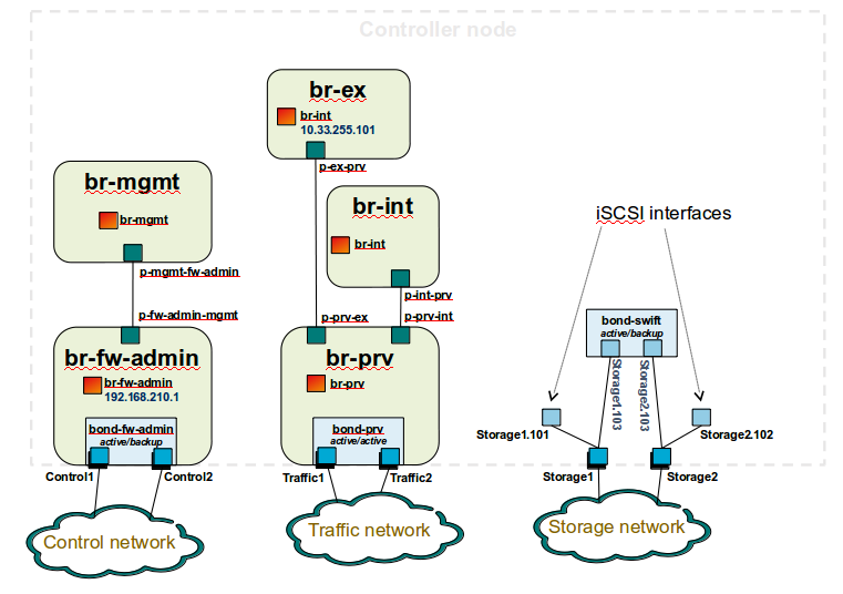
ontroller node bridge topology overview
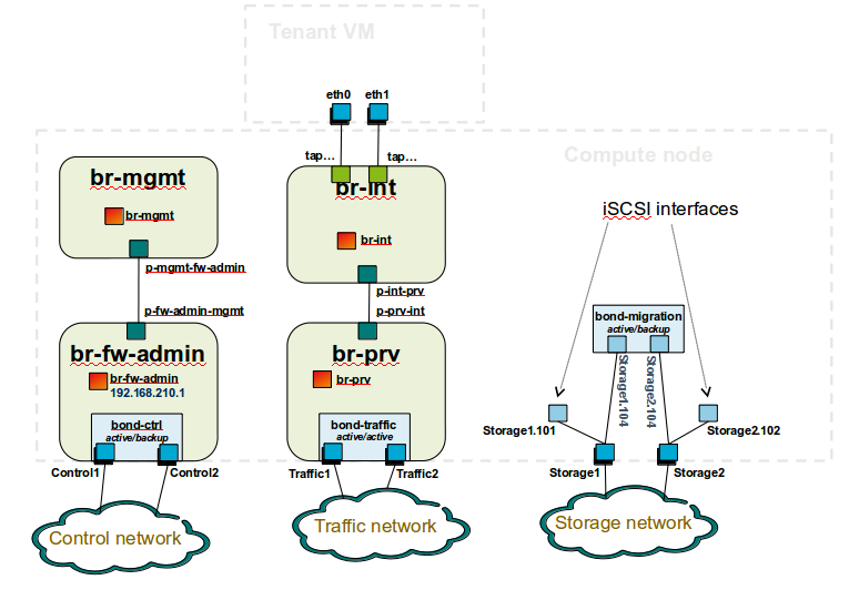
compute node bridge topology overview
Architecture
** Network Diagram **
The Pharos architecture may be described as follow: Figure 1: Standard Deployment Environment
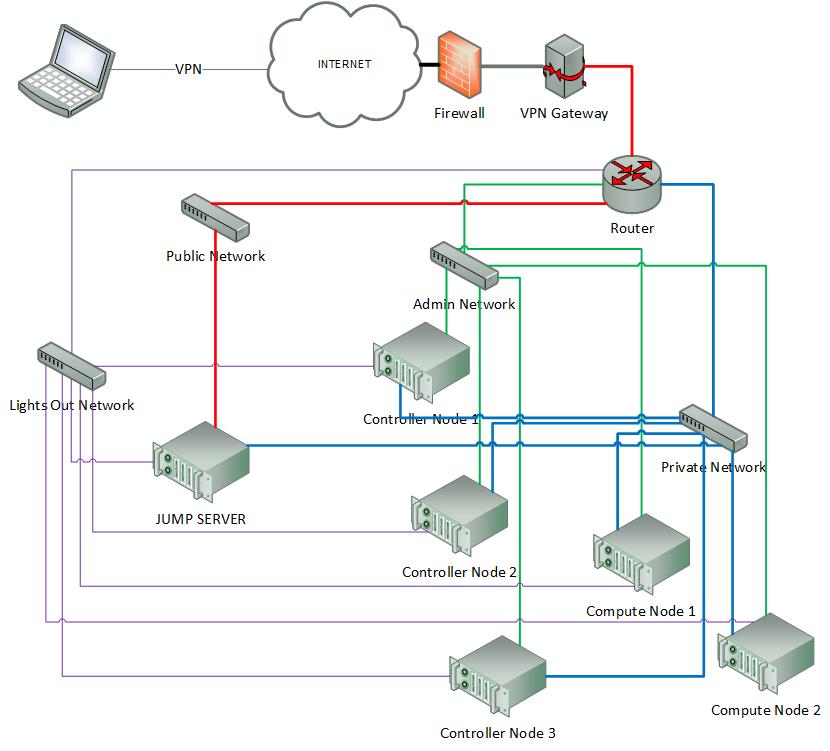
Figure 1: Standard Deployment Environment
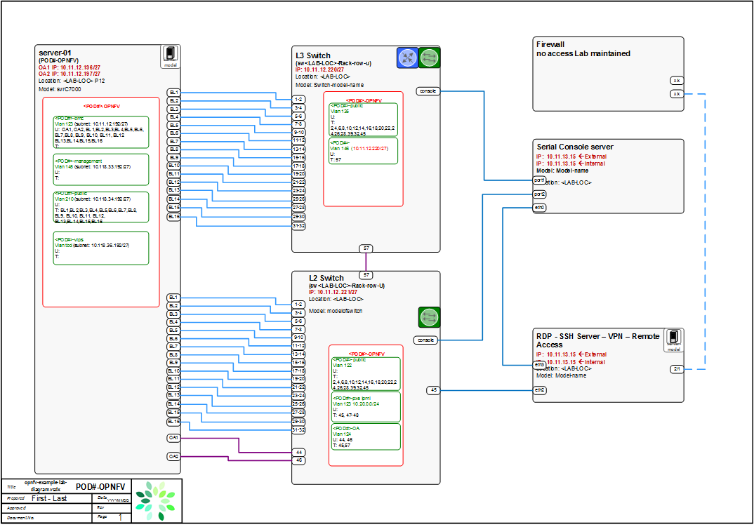
Sample Network Drawings
Files for documenting lab network layout. These were contributed as Visio VSDX format compressed as a ZIP file. Here is a sample of what the visio looks like.
Download the visio zip file here: opnfv-example-lab-diagram.vsdx.zip