Pharos Specification
Table of Contents
Objectives / Scope
The Pharos specification defines the OPNFV hardware environment upon which the OPNFV Arno platform release can be deployed on and tested. This specification defines:
- A secure, scalable, standard and HA environment
- Supports the full Arno deployment lifecycle (this requires a bare metal environment)
- Supports functional and performance testing of the Arno release
- Provides mechanisms and procedures for secure remote access to the test environment
Deploying Arno in a Virtualized environment is possible and will be useful, however it does not provide a fully featured deployment and test environment for the Arno release of OPNFV.
The high level architecture is outlined in the following diagram:
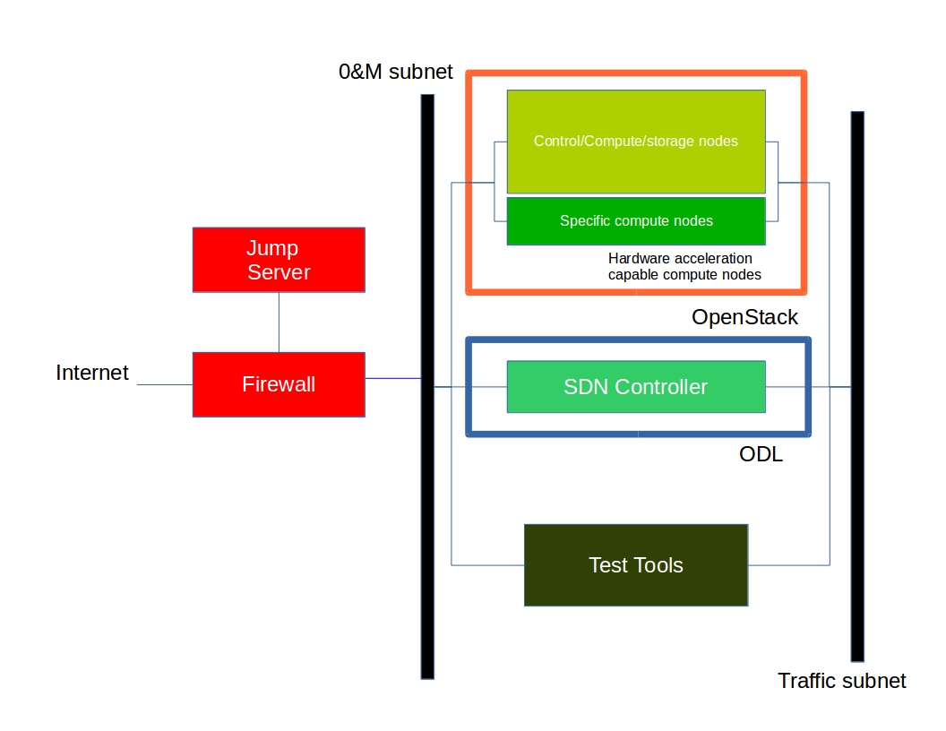
A Pharos compliant OPNFV test-bed environment provides
- One CentOS 7 jump server on which the virtualized Openstack/OPNFV installer runs
- In the Arno release you may select a deployment toolchain to deploy from the jump server from the Foreman and Fuel ISO images.
- 5 compute / controller nodes (BGS requires 5 nodes)
- A configured network topology allowing for LOM, Admin, Public, Private, and Storage Networks
- Remote access as defined by the Jenkins slave configuration guide http://artifacts.opnfv.org/arno.2015.1.0/docs/opnfv-jenkins-slave-connection.arno.2015.1.0.pdf
Hardware requirements
Servers
CPU:
- Intel Xeon E5-2600v2 Series (Ivy Bridge and newer, or similar)
Local Storage Configuration:
Below describes the minimum for the Pharos spec, which is designed to provide enough capacity for a reasonably functional environment. Additional and/or faster disks are nice to have and may produce a better result.
- Disks: 2 x 1TB + 1 x 100GB SSD
- The first 1TB HDD should be used for OS & additional software/tool installation
- The second 1TB HDD configured for CEPH object storage
- Finally, the 100GB SSD should be used as the CEPH journal
- Performance testing requires a mix of compute nodes that have CEPH(swift+Cinder) and without CEPH storage
- Virtual ISO boot capabilities or a separate PXE boot server (DHCP/tftp or Cobbler)
Memory:
- 32G RAM Minimum
Power Supply Single
- Single power supply acceptable (redundant power not required/nice to have)
Provisioning the jump server
- Obtain CentOS 7 Minimal ISO and install
wget http://mirrors.kernel.org/centos/7/isos/x86_64/CentOS-7-x86_64-Minimal-1503-01.iso
- Set parameters appropriate for your environment during installation
- Disable NetworkManager
systemctl disable NetworkManager
- Configure your /etc/sysconfig/network-scripts/ifcfg-* files for your network
- Restart networking
service network restart
- Edit /etc/resolv.conf and add a nameserver
vi /etc/resolv.conf
- Install libvirt & kvm
yum -y updateyum -y install kvm qemu-kvm libvirtsystemctl enable libvirtd
- Reboot:
shutdown -r now
- If you wish to avoid annoying delay when use ssh to log in, disable DNS lookups:
vi /etc/ssh/sshd_configUncomment “UseDNS yes”, change ‘yes’ to ‘no’. Save
- Restart sshd
systemctl restart sshd
- Install virt-install
yum -y install virt-install
- Begin the installation of the Arno release
Download your preferred ISO from the OPNFV dowloads page and follow the associated installation instructions.
Remote management
Remote access
- Remote access is required for …
- Developers to access deploy/test environments (credentials to be issued per POD / user)
- Connection of each environment to Jenkins master hosted by Linux Foundation for automated deployment and test
- OpenVPN is generally used for remote however community hosted labs may vary due to company security rules
- POD access rules / restrictions …
- Refer to individual test-bed as each company may have different access rules and acceptable usage policies
- Basic requirement is for SSH sessions to be established (initially on jump server)
- Majority of packages installed on a system (tools or applications) will be pulled from an external repo so this scenario must be accomodated.
Firewall rules should include
- SSH sessions
- Jenkins sessions
Lights-out Management:
- Out-of-band management for power on/off/reset and bare-metal provisioning
- Access to server is through lights-out-management tool and/or a serial console
- Intel lights-out ⇒ RMM http://www.intel.com/content/www/us/en/server-management/intel-remote-management-module.html
- HP lights-out ⇒ ILO http://www8.hp.com/us/en/products/servers/ilo/index.html
- CISCO lights-out ⇒ UCS https://developer.cisco.com/site/ucs-dev-center/index.gsp
- Dell lights-out ⇒ IDRAC http://en.community.dell.com/techcenter/systems-management/w/wiki/3204.dell-remote-access-controller-drac-idrac
Linux Foundation - VPN service for accessing Lights-Out Management (LOM) infrastructure for the UCS-M hardware
- People with admin access to LF infrastructure:
- amaged@cisco.com
- cogibbs@cisco.com
- daniel.smith@ericsson.com
- dradez@redhat.com
- fatih.degirmenci@ericsson.com
- fbrockne@cisco.com
- jonas.bjurel@ericsson.com
- jose.lausuch@ericsson.com
- joseph.gasparakis@intel.com
- morgan.richomme@orange.com
- pbandzi@cisco.com
- phladky@cisco.com
- stefan.k.berg@ericsson.com
- szilard.cserey@ericsson.com
- trozet@redhat.com
The people who require VPN access must have a valid PGP key bearing a valid signature from one of these three people. When issuing OpenVPN credentials, LF will be sending TLS certificates and 2-factor authentication tokens, encrypted to each recipient’s PGP key.
Networking
Test-bed network
- 24 or 48 Port TOR Switch
- NICS - 1GE, 10GE - per server can be on-board or PCI-e
- Connectivity for each data/control network is through a separate NIC. This simplifies Switch Management however requires more NICs on the server and also more switch ports
- Lights-out network can share with Admin/Management
Network Interfaces
- Option I: 4x1G Control, 2x40G Data, 48 Port Switch
- 1 x 1G for ILMI (Lights out Management)
- 1 x 1G for Admin/PXE boot
- 1 x 1G for control Plane connectivity
- 1 x 1G for storage
- 2 x 40G (or 10G) for data network (redundancy, NIC bonding, High bandwidth testing)
- Option II: 1x1G Control, 2x 40G (or 10G) Data, 24 Port Switch
- Connectivity to networks is through VLANs on the Control NIC. Data NIC used for VNF traffic and storage traffic segmented through VLANs
- Option III: 2x1G Control, 2x10G Data, 2x40G Storage, 24 Port Switch
- Data NIC used for VNF traffic, storage NIC used for control plane and Storage segmented through VLANs (separate host traffic from VNF)
- 1 x 1G for IPMI
- 1 x 1G for Admin/PXE boot
- 2 x 10G for control plane connectivity/Storage
- 2 x 40G (or 10G) for data network
Documented configuration to include: - Subnet, VLANs (may be constrained by existing lab setups or rules) - IPs - Types of NW - lights-out, public, private, admin, storage - May be special NW requirements for performance related projects - Default gateways
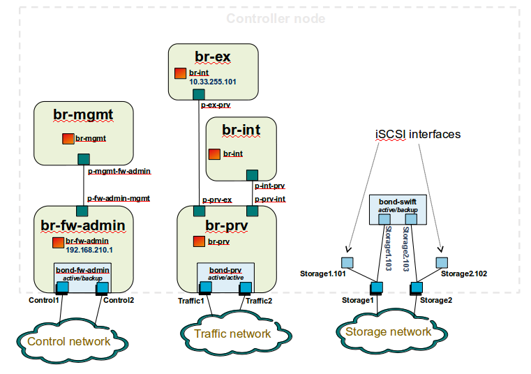
Controller node bridge topology overview
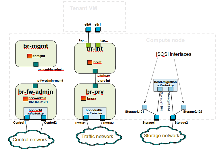
compute node bridge topology overview
Architecture
Network Diagram
The Pharos architecture may be described as follow: Figure 1: Standard Deployment Environment
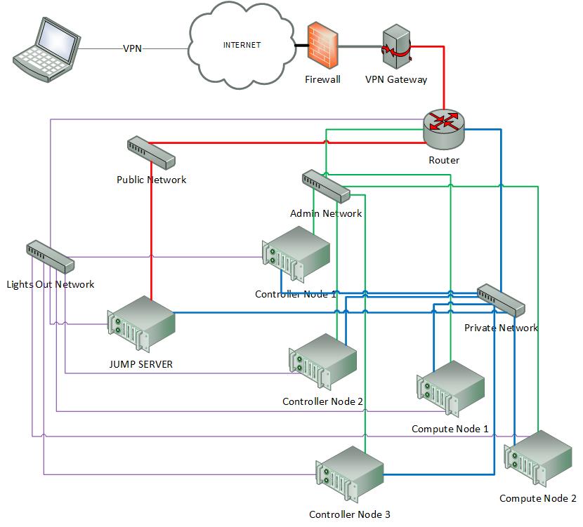
Figure 1: Standard Deployment Environment
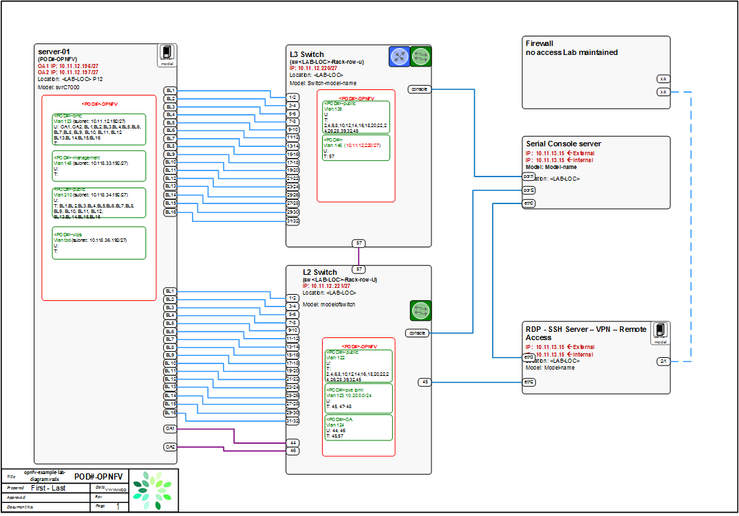
Sample Network Drawings
Files for documenting lab network layout. These were contributed as Visio VSDX format compressed as a ZIP file. Here is a sample of what the visio looks like.
Download the visio zip file here: opnfv-example-lab-diagram.vsdx.zip
| Authors: | Trevor Cooper (Intel) |
|---|---|
| Version: | 1.0 |
