2.1. L3VPN Use Cases
Service Providers’ virtualized network infrastructure may consist of one or more SDN Controllers from different vendors. Those SDN Controllers may be managed within one cloud or multiple clouds. Jointly, those VIMs (e.g. OpenStack instances) and SDN Controllers work together in an interoperable framework to create L3 services in Service Providers’ virtualized network infrastructure.
Three use cases of creating L3VPN service by multiple SDN Controllers are described as follows.
2.1.1. Any-to-Any Base Case
2.1.1.1. Description
There are 2 hosts (compute nodes). SDN Controller A and vRouter A are provided by Vendor A, and run on host A. SDN Controller B and vRouter B are provided by Vendor B, and run on host B.
There are 2 tenants. Tenant 1 creates L3VPN Blue with 2 subnets: 10.1.1.0/24 and 10.3.7.0/24. Tenant 2 creates L3VPN Red with 1 subnet, overlapping address space: 10.1.1.0/24.
The network topology is shown in Fig. 2.1:
In L3VPN Blue, VMs G1 (10.1.1.5) and G2 (10.3.7.9) are spawned on host A, and attached to 2 subnets (10.1.1.0/24 and 10.3.7.0/24) and assigned IP addresses respectively. VMs G3 (10.1.1.6) and G4 (10.3.7.10) are spawned on host B, and attached to 2 subnets (10.1.1.0/24 and 10.3.7.0/24) and assigned IP addresses respectively.
In L3VPN Red, VM G5 (10.1.1.5) is spawned on host A, and attached to subnet 10.1.1.0/24. VM G6 (10.1.1.6) is spawned on host B, and attached to the same subnet 10.1.1.0/24.
VRF Lets us do:
- Overlapping Addresses
- Segregation of Traffic
2.1.1.2. Derrived Requirements
- TBD
2.1.1.2.1. Northbound API / Workflow
Exemplary workflow is described as follows:
- Create Network
- Create Network VRF Policy Resource
Any-to-Any
2.1. This sets up that when this tenant is put on a HOST that:
2.1.1. There will be a RD assigned per VRF
2.1.2. There will be a RT used for the common any-to-any communication
- Create Subnet
- Create Port (subnet, network vrf policy resource). This causes controller to:
4.1. Create vrf in vRouter’s FIB, or Update vrf if already exists
4.2. Install an entry for Guest’s HOST-Route in FIBs of Vrouters serving this tenant Virtual Network
4.3. Announce Guest HOST-Route to WAN-GW via MP-BGP
2.1.1.2.2. Data model objects
- TBD
2.1.1.2.3. Orchestration
- TBD
2.1.1.2.4. Dependencies on compute services
- TBD
2.1.1.3. Potential implementation
Support for creating and managing L3VPNs is available in OpenStack Neutron by means of the BGPVPN project [BGPVPN]. In order to create the L3VPN network configuration described above using the API BGPVPN API, the following workflow is needed:
- Create a Neutron network “blue”
neutron net-create blue
- Create the first Neutron subnet of the network “blue”
neutron subnet-create <blue network UUID> 10.1.1.0/24
- Create the second Neutron subnet of the network “blue”
neutron subnet-create <blue network UUID> 10.3.7.0/24
- Create a L3VPN by means of the BGPVPN API
neutron bgpvpn-create --route-targets 64512:1 --tenant-id <tenant-id> --name blue
- Associate the L3VPN with the previously created network
neutron bgpvpn-net-assoc-create blue --network <network-UUID>This command associates the given Neutron network with the L3VPN. The semantic of this operation is that all subnets bound to the network are getting interconnected through the BGP VPN and hence VMs located in either subnet can communicate with each other.
2.1.1.4. Gaps in the current solution
TBD
2.1.1.5. Conclusion
TBD
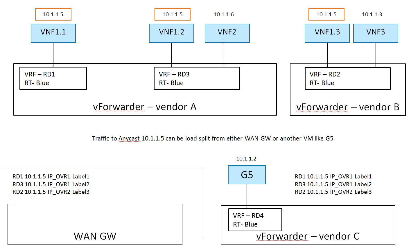
2.1.2. ECMP Load Splitting Case (Anycast)
2.1.2.1. Description
There are 2 hosts (compute nodes). SDN Controller A and vRouter A are provided by Vendor A, and run on host A. SDN Controller B and vRouter B are provided by Vendor B, and run on host B.
There is 1 tenant. Tenant 1 creates L3VPN Blue with subnet 10.1.1.0/24.
The network topology is shown in Fig. 2.2:
In L3VPN Blue, VNF1.1 and VNF1.2 are spawned on host A, attached to subnet 10.1.1.0/24 and assigned the same IP address 10.1.1.5. VNF1.3 is spawned on host B, attached to subnet 10.1.1.0/24 and assigned the same IP addresses 10.1.1.5. VNF 2 and VNF 3 are spawned on host A and B respectively, attached to subnet 10.1.1.0/24, and assigned different IP addresses 10.1.1.6 and 10.1.1.3 respectively.
Here, the Network VRF Policy Resource is ECMP/AnyCast. Traffic to Anycast 10.1.1.5
can be load split from either WAN GW or another VM like G5.
2.1.3. Hub and Spoke Case
2.1.3.1. Description
There are 2 hosts (compute nodes). SDN Controller A and vRouter A are provided by Vendor A, and run on host A. SDN Controller B and vRouter B are provided by Vendor B, and run on host B.
There is 1 tenant. Tenant 1 creates L3VPN Blue with 2 subnets: 10.1.1.0/24 and 10.3.7.0/24.
The network topology is shown in Fig. 2.3:
In L3VPN Blue, vFW(H) is acting the role of hub (a virtual firewall).
The other 3 VNFsVMs are spoke. vFW(H) and VNF1(S) are spawned on host A,
and VNF2(S) and VNF3(S) are spawned on host B. vFW(H) (10.1.1.5) and VNF2(S)
(10.1.1.6) are attached to subnet 10.1.1.0/24. VNF1(S) (10.3.7.9) and VNF3(S)
(10.3.7.10) are attached to subnet 10.3.7.0/24.
Exemplary vFW(H) Hub VRF is as follows:
- RD1 10.1.1.5 IP_OVR1 Label1
- RD1 0/0 IP_OVR1 Label1
- Label 1 Local IF (10.1.1.5)
- RD3 10.3.7.9 IP_OVR1 Label2
- RD2 10.1.1.6 IP_OVR2 Label3
- RD4 10.3.7.10 IP_OVR2 Label3
Exemplary VNF1(S) Spoke VRF is as follows:
- RD1 0/0 IP_OVR1 Label1
- RD3 10.3.7.9 IP_OVR1 Label2
Exemplary workflow is described as follows:
- Create Network
- Create VRF Policy Resource
2.1. Hub and Spoke
- Create Subnet
- Create Port
4.1. Subnet
4.2. VRF Policy Resource, [H | S]


