3. Modelling
It is necessary to clearly define the infrastructure resources and their capabilities that a shared cloud infrastructure (network function virtualisation infrastructure, NFVI) provides for hosting workloads including virtual network functions (VNFs) and/or cloud-native network functions (CNFs). A common understanding of which resources and their corresponding capabilities a cloud infrastructure provides or shall provide will help improve workload onboarding efficiency and avoid issues that could negatively impact the time and the cost of onboarding and maintaining target workloads and solutions on top of a virtualised infrastructure.
The abstraction model presented in this Reference Model (RM) specifies a common set of virtual infrastructure resources that a cloud infrastructure will need to provide to be able to host most of the typical VNF/CNF telco workloads. The intention of this Reference Model is to follow the following principles:
Scope: the model should describe the most relevant virtualised infrastructure resources (incl. acceleration technologies) a cloud infrastructure needs to host Telco workloads
Separation of Concern: the model should support a clear distinction between the responsibilities related to maintaining the network function virtualisation infrastructure and the responsibilities related to managing the various VNF workloads
Simplicity: the amount of different types of resources (including their attributes and relationships amongst one another) should be kept to a minimum to reduce the configuration spectrum which needs to be considered
Declarative: the model should allow for the description of the intended state and configuration of the cloud infrastructure resources for automated life cycle management
Explicit: the model needs to be rich enough to cover the instantiation and the on-going operation of the cloud infrastructure
Lifecycle: the model must distinguish between resources which have independent lifecycles but should group together those resources which share a common lifecycle
Aligned: the model should clearly highlight the dependencies between its components to allow for a well-defined and simplified synchronisation of independent automation tasks.
To summarise:the abstraction model presented in this document will build upon existing modelling concepts and simplify and streamline them to the needs of telco operators who intend to distinguish between infrastructure related and workload related responsibilities.
3.1. Model
The abstraction model for the cloud infrastructure is divided into two logical layers: the virtual infrastructure layer and the hardware infrastructure layer, with the intention that only the virtual infrastructure layer will be directly exposed to workloads (VNFs/CNFs):
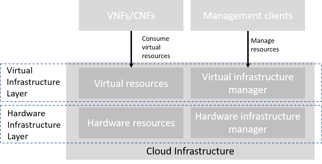
Figure 3.1 Cloud Infrastructure Model Overview
The functionalities of each layer are as follows:
Virtual Infrastructure Layer
Virtual infrastructure resources: These are all the infrastructure resources (compute, storage and networks) which the cloud infrastructure provides to the VNF/CNF and other workloads. These virtual resources can be managed by the tenants and tenant workloads directly or indirectly via an application programming interface (API).
Virtual infrastructure manager: This consists of the software components that manage the virtual resources and make those management capabilities accessible via one or more APIs. The responsibilities of this functionality include the management of logical constructs such as tenants, tenant workloads, resource catalogues, identities, access controls, security policies, etc.
Hardware Infrastructure Layer
Hardware infrastructure manager: This is a logical block of functionality responsible for the management of the abstracted hardware resources (compute, network and storage) and as such it is shielded from the direct involvement with server host software.
Hardware resources: These consist of physical hardware components such as servers, (including random access memory, local storage, network ports, and hardware acceleration devices), storage devices, network devices, and the basic input output system (BIOS).
Workload Layer
Workloads (VNFs/CNFs): These consist of workloads such as virtualized and/or containerized network functions that run within a virtual machine (VM) or as a set of containers.
3.2. Virtual Infrastructure Layer
3.2.1. Virtual Resources
The virtual infrastructure resources provided by the Cloud Infrastructure can be grouped into four categories as shown in the diagram below:
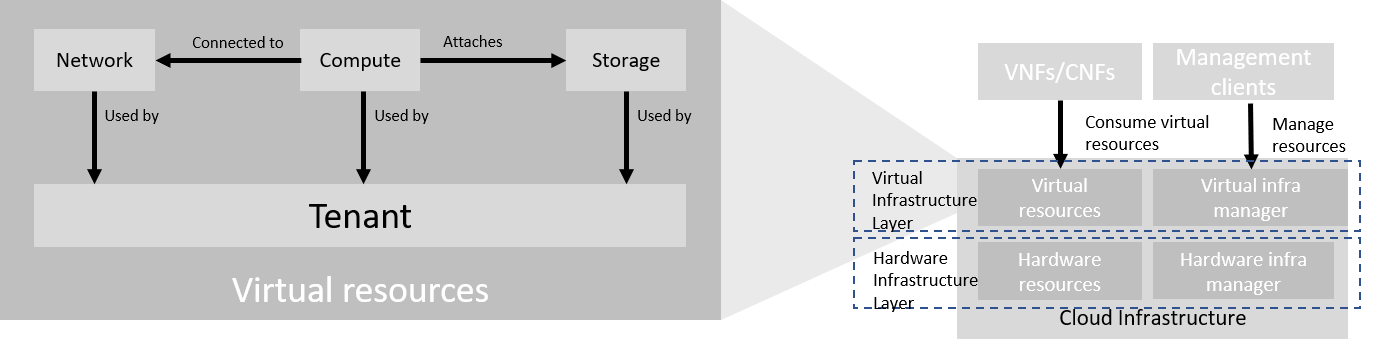
Figure 3.2 Virtual Infrastructure Resources provide virtual compute, storage and networks in a tenant context
Tenants: represent an isolated and independently manageable elastic pool of compute, storage and network resources
Compute resources: represent virtualised computes for workloads and other systems as necessary
Storage resources: represent virtualised resources for persisting data
Network resources: represent virtual resources providing layer 2 and layer 3 connectivity
The virtualised infrastructure resources related to these categories are listed below.
3.2.1.1. Tenant
A cloud infrastructure needs to be capable of supporting multiple tenants and has to isolate sets of infrastructure resources dedicated to specific workloads (VNF/CNF) from one another. Tenants represent an independently manageable logical pool of compute, storage and network resources abstracted from physical hardware.
Example: a tenant within an OpenStack environment or a Kubernetes cluster.
Attribute |
Description |
|---|---|
|
name of the logical resource pool |
|
type of tenant (e.g. OpenStack tenant, Kubernetes cluster, …) |
|
max. number of virtual CPUs |
|
max. size of random access memory in GB |
|
max. size of ephemeral disk in GB |
|
description of external networks required for inter-domain connectivity |
|
key/value pairs for selection of the appropriate physical context (e.g. location, availability zone, …) |
Table 3-1: Attributes of a tenant
3.2.1.2. Virtual Compute
A virtual machine or a container/pod capable of hosting the application components of workloads (VNFs/CNFs) of the tenant. A virtual compute therefore requires a tenant context and, since it will need to communicate with other communication partners, it is assumed that the networks have been provisioned in advance.
Example: a virtual compute descriptor as defined in TOSCA Simple Profile for NFV.
Attribute |
Description |
|---|---|
|
name of the virtual host |
|
number of virtual CPUs |
|
size of random access memory in GB |
|
size of root disc in GB |
|
sorted list of network interfaces connecting the host to the virtual networks |
|
key/value pairs for selection of the appropriate acceleration technology |
|
key/value pairs for selection of the appropriate redundancy domain |
Table 3-2: Attributes of compute resources
3.2.1.3. Virtual Storage
A virtual machine and container can consume storage through a number of means. These include storage that is:
managed via the hypervisor and container runtime (Hypervisor Attached for virtual machine and Container Persistent for containers) and is connected via cloud infrastructure underlay network and
Shared File Storage and the Object storage which is connected via the tenant / user overlay network. The details of the tenant storage consumption model are covered in section Virtual Storage.
In managing the provision of virtual storage the tenant should be able to request alternate performance levels, capacity and behaviours. The set of selectable attributes includes:
Storage class: Block, File, Object.
Retention Policy - persistent (storage volume / data) is persistent across stop/start of workload; ephemeral storage - there is no data retention across stop/start events for the workload.
Underlying physical device type (HDD, SSD, etc.).
Performance characteristic - defined as: Latency, IOPS (Input/Output Operations per second), and throughput.
Enhanced features - set of selectable features such as: auto-replicate, encryption, snapshot support.
Note that approximate numeric ranges for the qualitative values used above are given in the Storage Extensions section.
Storage resources have the following attributes, with metric definitions that support verification through passive measurements (telemetry) where appropriate:
Attribute |
Description |
|---|---|
|
name of storage resources |
|
persistent or ephemeral |
|
Read and Write Latency, The average amount of time to perform a R/W operation, in milliseconds |
Read and Write IOPS, The average rate of performing R/W in IO operations per second |
|
Read and Write Throughput, The average rate of performing R/W operations in Bytes per second |
|
|
replication, encryption |
|
block, object or file |
|
size in GB, telemetry includes the amount of free, used, and reserved disk space, in bytes |
Table 3-3: Attributes of storage resources
3.2.1.4. Virtual Network
This topic is covered in Network section.
3.2.1.5. Availability Zone
An availability zone is a logical pool of physical resources (e.g. compute, block storage, and network). These logical pools segment the physical resources of a cloud based on factors chosen by the cloud operator. The cloud operator may create availability zones based on location (rack, datacenter), or indirect failure domain dependencies like power sources. Workloads can leverage availability zones to utilise multiple locations or avoid sharing failure domains for a workload, and thus increase the workloads’ fault-tolerance.
As a logical group with operator-specified criteria, the only mandatory attribute for an Availability Zone is the name.
Attribute |
Description |
|---|---|
|
name of the availability zone |
Table 3-4: Attributes of availability zones
3.2.2. Virtual Infrastructure Manager
The virtual infrastructure manager allows:
setup, manage and delete tenants,
setup, manage and delete user- and service-accounts,
manage access privileges and
provision, manage, monitor and delete virtual resources.
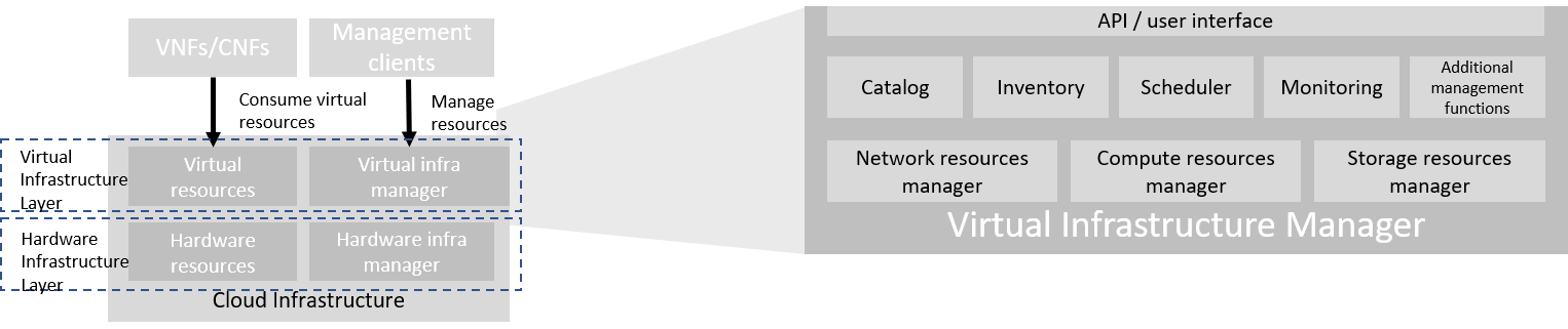
Figure 3.3 Virtual Infrastructure Manager
The virtual infrastructure manager needs to support the following functional aspects:
API/UI: an application programming interface / user interface providing access to the virtual resource management function
Catalogue: manages the collection of available templates for virtual resource the cloud infrastructure can provide
Inventory: manages the information related to virtual resources of a cloud infrastructure
Scheduler: receives requests via API/UI, provisions and manages virtual resources by coordinating the activities of the compute-, storage- and network resources managers
Monitoring: monitors and collects information on all events and the current state of all virtual resources
Additional Management Functions: include identity management, access management, policy management (e.g. to enforce security policies), etc.
Compute Resources Manager: provides a mechanism to provision virtual resources with the help of hardware compute resources
Storage Resources Manager: provides a mechanism to provision virtual resources with the help of hardware storage resources
Network Resources Manager: provides a mechanism to provision virtual resources with the help of hardware network resources
3.3. Hardware Infrastructure Layer
3.3.1. Hardware Infrastructure Resources
Compute, Storage and Network resources serve as the foundation of the cloud infrastructure. They are exposed to and used by a set of networked Host Operating Systems in a cluster that normally handles the Virtual Infrastructure Layer offering Virtual Machines or Containers where the application workloads (VNFs/CNFs) runs.
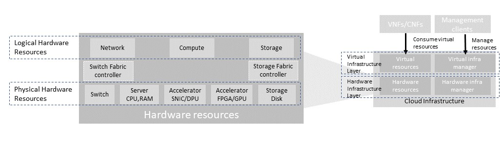
Figure 3.4 Cloud Infrastructure Hardware Resources
In managed Hardware Infrastructure systems, these consumable Compute, Storage and Network resources can be provisioned through operator commands or through software APIs. There is a need to distinguish between these consumable resources, that are treated as leased resources, from the actual physical hardware resources that are installed in the data centre. For this purpose, the hardware resource layer is conceptually split into a Logical Resource Layer that surfaces the consumable resources to the software layer above, and the Physical Resource Layer that is operated and managed by the Cloud Infrastructure Providers Operations team from the Hardware Infrastructure Management functions perspective.
Some installations might use a cluster of managed switches or storage components controlled by a Switch Fabric controller and/or a Storage Fabric controller acting as an appliance system. These systems should be federated with the HW Infrastructure Management system over some API to facilitate exchange of configuration intent, status and telemetry information allowing the Hardware Infrastructure Management and Management stack to automate Cloud Infrastructure operations. These appliance systems normally also have their own Equipment Management APIs and procedures for the hardware installation and maintenance staff.
An example could be a Cloud Infrastructure stack federated with a commercial Switch Fabric where the Cloud Infrastructure shall be able to “send” networking configuration intent to the Switch Fabric and the Switch Fabric shall be able to “send” (see note below) status and telemetry information to the Cloud Infrastructure e.g. Port/Link Status and packet counters of many sorts. This allows Hardware Infrastructure Management and Cloud Infrastructure management stack to have network automation that includes the switches that are controlled by the federated Switch Fabric. This would be a rather normal case for Operators that have a separate Networking Department that owns and runs the Switch Fabric separately from the Data Centre.
NOTE: The word “send” is a very lose definition of getting a message across to the other side, and could be implemented in many different ways.
3.3.1.1. Hardware Acceleration Resources
For a given software network function and software infrastructure, Hardware Acceleration resources can be used to achieve requirements or improve cost/performance. Following table gives reasons and examples for using Hardware Acceleration.
Reason for using Hardware Acceleration |
Example |
Comment |
|---|---|---|
Achieve technical requirements |
Strict latency or timing accuracy |
Must be done by optimizing compute node; cannot be solved by adding more compute nodes |
Achieve technical requirements |
Fit within power or space envelope |
Done by optimizing cluster of compute nodes |
Improve cost/performance |
Better cost and less power/cooling by improving performance per node |
Used when functionality can be achieved through usage of accelerator or by adding more compute nodes |
Table 3-5: Reasons and examples for using Hardware Acceleration
Hardware Accelerators can be used to offload software execution for purpose of accelerating tasks to achieve faster performance, or offloading the tasks to another execution entity to get more predictable execution times, efficient handling of the tasks or separation of authority regarding who can control the tasks execution.
More details about Hardware Acceleration are in Hardware Acceleration Abstraction.
3.3.2. Hardware Infrastructure Manager
The HW Infrastructure Manager shall at least support equipment management for all managed physical hardware resources of the Cloud Infrastructure.
In most deployments the Hardware Infrastructure Manager should also be the HW Infrastructure Layer provisioning manager of the Compute, Storage and Network resources that can be used by the Virtualization Infrastructure Layer instances. It shall provide an API enabling vital resource recovery and control functions of the provisioned functions e.g. Reset and Power control of the Computes.
For deployments with more than one Virtualization Infrastructure Layer instance that will be using a common pool of hardware resources there is a need for a HW Infrastructure Layer provisioning manager of the Compute, Storage and Network resources to handle the resource assignment and arbitration.
The resource allocation could be a simple book-keeping of which Virtualization Infrastructure Layer instance that have been allocated a physical hardware resource or a more advanced resource Composition function that assemble the consumed Compute, Storage and Network resources on demand from the pools of physical hardware resources.
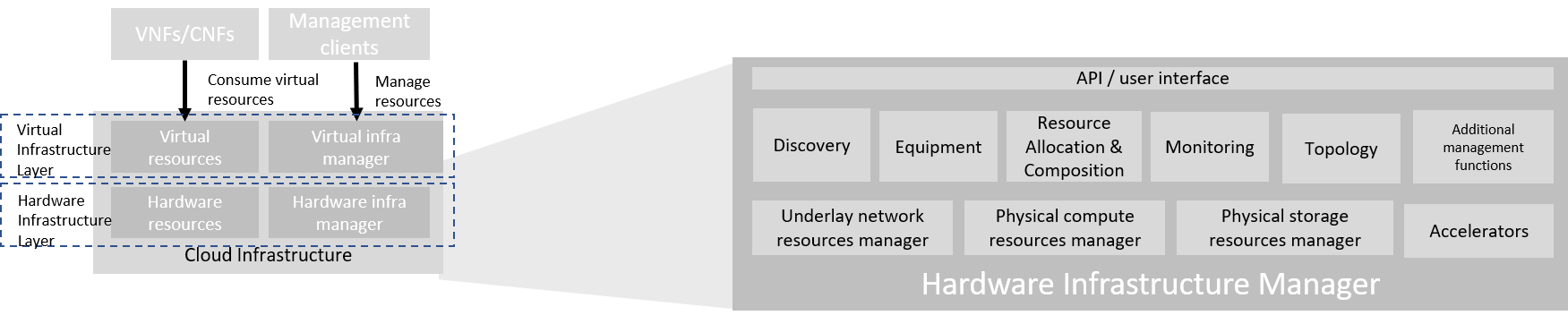
Figure 3.5 Hardware Infrastructure Manager
The hardware infrastructure manager allows to:
provision, manage, monitor and delete hardware resources
manage physical hardware resource discovery, monitoring and topology
manage hardware infrastructure telemetry and log collection services
The hardware infrastructure manager needs to support the following functional aspects:
API/UI: an application programming interface / user interface providing access to the hardware resource management functions
Discovery: discover physical hardware resources and collect relevant information about them
Topology: discover and monitor physical interconnection (e.g. cables) in between the physical hardware resources
Equipment: manages the physical hardware resources in terms of configuration, firmware status, health/fault status and autonomous environmental control functions such as fan and power conversion regulations
Resource Allocation and Composition: creates, modifies and deletes logical Compute, Network and Storage Resources through Composition of allocated physical hardware resources
Underlay Network Resources Manager: provides a mechanism to provision hardware resources and provide separation in between multiple Virtualization Infrastructure instances for the use of the underlay network (e.g. switch fabric, switches, SmartNICs)
Monitoring: monitors and collects information on events, current state and telemetry data of physical hardware resources, autonomous equipment control functions as well as Switch and Storage Fabric systems
Additional Management Functions: include software and configuration life cycle management, identity management, access management, policy management (e.g. to enforce security policies), etc.
3.4. Left for future use
This section is left blank for future use
3.5. Network
Networking, alongside Compute and Storage, is an integral part of the Cloud Infrastructure (Network Function Virtualisation Infrastructure). The general function of networking in this context is to provide the connectivity between various virtual and physical resources required for the delivery of a network service. Such connectivity may manifest itself as a virtualised network between VMs and/or containers (e.g. overlay networks managed by SDN controllers, and/or programmable network fabrics) or as an integration into the infrastructure hardware level for offloading some of the network service functionality.
Normalization of the integration reference points between different layers of the Cloud Infrastructure architecture is one of the main concerns. In the networking context the primary focus is directed on the packet flow and control flow interfaces between the virtual resources (referred to as Software (SW) Virtualisation Layer) and physical resources (referred to as Hardware (HW) Infrastructure Layer), as well as on related integration into the various MANO reference points (hardware/network infrastructure management, orchestration). The identification of these two different layers (SW Virtualisation Layer and HW Infrastructure Layer) remains in alignment with the separation of resources into virtual and physical resources, generally used in this document, see e.g., Figure 3.1. The importance of understanding the separation of concerns between SW Virtualisation Layer and HW Infrastructure Layer is important because without it, the cardinality of having multiple CaaS and IaaS instances executing on their own private virtual resources from the single shared HW Infrastructure Layer cannot be expressed into separate administrative domains.
3.5.1. Network Principles
Principles that should be followed during the development and definition of the networking scope for the Reference Model, Reference Architectures, Reference Implementations and Reference Conformance test suites:
Abstraction: A standardized network abstraction layer between the Virtualisation Layers and the Network Physical Resources Layer that hides (or abstracts) the details of the Network Physical resources from the Virtualisation Layers.
Note: In deployment phases this principle may be applied in many different ways e.g. depending on target use case requirements, workload characteristics, different algorithm implementations of pipeline stages and available platforms. The network abstraction layer supports, for example, physical resources with or without programmable hardware acceleration, or programmable network switches
Agnosticism: Define Network Fabric concepts and models that can carry any type of traffic in terms of:
Control, User and Management traffic types
Acceleration technologies that can support multiple types of infrastructure deployments and network function workloads
Automation: Enable end-to-end automation, from Physical Fabric installation and provisioning to automation of workloads (VNF/CNF) onboarding.
Openness: All networking is based on open source or standardized APIs (North Bound Interfaces (NBI) and South Bound Interfaces (SBI)) and should enable integration of open source networking components such as SDN controllers.
Programmability: Network model enables a programmable forwarding plane controlled from a separately deployed control plane.
Scalability: Network model enables scalability to handle all traffic traverse North-South and East-West enabling small up to large deployments in a non-blocking manner.
Workload agnostic: Network model is capable of providing connectivity to any type of workloads, including VNF, CNF and BareMetal workloads.
Carrier Grade: Network model is capable of supporting deployments of the carrier grade workloads.
Future proof: Network model is extendible to support known and emerging technology trends including SmartNICs, FPGAs and Programmable Switches, integrated for multi-clouds, and Edge related technologies.
3.5.2. Network Layering and Concepts
The Cloud Infrastructure Networking Reference Model is an essential foundation that governs all Reference Architectures and Cloud Infrastructure implementations to enable multiple cloud infrastructure virtualisation technology choices and their evolution. These include:
Single Infrastructure as a Service (IaaS) based virtualisation instances with Virtual Machines (VM)
Multi IaaS based virtualisation instances
Cloud Native Container as a Service (CaaS) based virtualisation instances, and
Hybrid multi IaaS and CaaS based virtualisation instances
To retain the cloud paradigms of automation, scalability and usage of shared hardware resources when introducing CaaS instances it is necessary to enable an ability to co-deploy multiple simultaneous IaaS and CaaS instances on a shared pool of hardware resources.
Compute and Storage resources are rarely shared in between IaaS or CaaS instances, but the underpinning networking, most commonly implemented with Ethernet and IP, must be shared and managed as a shared pool of underlay network resources to enable the pooled usage of Compute and Storage from a managed shared pool.
Throughout this chapter and its figures a number of references to ETSI NFV are made and they explicitly are made towards the ETSI NFV models in the Architectural Framework:
ETSI GS NFV 002 V1.2.1 [3]
ETSI GR NFV-IFA 029 V3.3.1 [4]
Cloud and Telco networking are layered, and it is very important to keep the dependencies between the layers low to enable security, separation and portability in between multiple implementations and generations.
Before we start developing a deep model we need to agree on some foundational concepts and layering that allow decoupling of implementations in between the layers. We will emphasize four concepts in this section:
Underlay and Overlay Networking concepts
Hardware and Virtual Infrastructure Layer concepts
Software Defined Underlay and Overlay Networking concepts
Programmable Networking Fabric concept
3.5.2.1. Underlay and Overlay Networking Concepts
The ETSI Network Functions Virtualisation Architectural Framework (as referred above) describes how a Virtual Infrastructure Layer instance abstracts the hardware resources and separates Virtualisation Tenants (Workload) from each other. It does also specifically state that the control and implementation of the hardware layer is out of scope for that specification.
When having multiple Virtual Infrastructure Layer instances on a shared hardware infrastructure, the networking can be layered in an Underlay and an Overlay Network layer. The purpose with this layering is to ensure separation of the Virtualisation Tenants (Workload) Overlay Networks from each other, whilst allowing the traffic to flow on the shared Underlay Network in between all Ethernet connected hardware (HW) devices.
The Overlay Networking separation is often done through encapsulation of Tenants traffic using overlay protocols e.g. through VxLAN or EVPN on the Underlay Networks e.g. based on L2 (VLAN) or L3 (IP) networks.
The Overlay Network for each Cloud Infrastructure deployment must support a basic primary Tenant Network between the Instances within each Tenant. Due to the nature of Telecom applications handling of Networks and their related Network Functions they often need access to external non-translated traffic flows and have multiple separated or secondary traffic channels with abilities for different traffic treatments.
In some instances, the Virtualisation Tenants can bypass the Overlay Networking encapsulation to achieve better performance or network visibility/control. A common method to bypass the Overlay Networking encapsulation normally done by the Virtualisation Layer, is the VNF/CNF usage of SR-IOV that effectively take over the Physical and Virtual Functions of the NIC directly into the VNF/CNF Tenant. In these cases, the Underlay Networking must handle the separation e.g. through a Virtual Termination End Point (VTEP) that encapsulate the Overlay Network traffic.
Note: Bypassing the Overlay Networking layer is a violation of the basic decoupling principles, but is in some cases unavoidable with existing technologies and available standards. Until suitable technologies and standards are developed, a set of agreed exemptions has been agreed that forces the Underlay Networking to handle the bypassed Overlay Networking separation.
VTEP could be manually provisioned in the Underlay Networking or be automated and controlled through a Software Defined Networking controller interfaces into the underlying networking in the HW Infrastructure Layer.
3.5.2.2. Hardware and Virtual Infrastructure Layer Concepts
The Cloud Infrastructure (based on ETSI NFV Infrastructure with hardware extensions) can be considered to be composed of two distinct layers, here referred to as HW Infrastructure Layer and Virtual Infrastructure Layer. When there are multiple separated simultaneously deployed Virtual Infrastructure domains, the architecture and deployed implementations must enable each of them to be in individual non-dependent administrative domains. The HW Infrastructure must then also be enabled to be a fully separated administrative domain from all of the Virtualisation domains.
For Cloud Infrastructure implementations of multiple well separated simultaneous Virtual Infrastructure Layer instances on a shared HW Infrastructure there must be a separation of the hardware resources i.e. servers, storage and the Underlay Networking resources that interconnect the hardware resources e.g. through a switching fabric.
To allow multiple separated simultaneous Virtual Infrastructure Layer instances onto a shared switching fabric there is a need to split up the Underlay Networking resources into non overlapping addressing domains on suitable protocols e.g. VxLAN with their VNI Ranges. This separation must be done through an administrative domain that could not be compromised by any of the individual Virtualisation Infrastructure Layer domains either by malicious or unintentional Underlay Network mapping or configuration.
These concepts are very similar to how the Hyperscaler Cloud Providers (HCP) offer Virtual Private Clouds for users of Bare Metal deployment on the HCP shared pool of servers, storage and networking resources.
The separation of Hardware and Virtual Infrastructure Layers administrative domains makes it important that the Reference Architectures do not include direct management or dependencies of the pooled physical hardware resources in the HW Infrastructure Layer e.g. servers, switches and underlay networks from within the Virtual Infrastructure Layer. All automated interaction from the Virtual Infrastructure Layer implementations towards the HW Infrastructure with its shared networking resources in the HW Infrastructure Layer must go through a common abstracted Reference Model interface.
3.5.2.3. Software Defined Underlay and Overlay Networking Concepts
A major point with a Cloud Infrastructures is to automate as much as possible. An important tool for Networking automation is Software Defined Networking (SDN) that comes in many different shapes and can act on multiple layers of the networking. In this section we will deal with the internal networking of a datacentre and not how datacentres interconnect with each other or get access to the world outside of a datacentre.
When there are multiple simultaneously deployed instances of the Virtual Infrastructure Layers on the same HW Infrastructure, there is a need to ensure Underlay networking separation in the HW Infrastructure Layer. This separation can be done manually through provisioning of a statically configured separation of the Underlay Networking in the HW Infrastructure Layer. A better and more agile usage of the HW Infrastructure is to offer each instance of the Virtual Infrastructure Layer a unique instance of a SDN interface into the shared HW Infrastructure. Since these SDN instances only deal with a well separated portion (or slice) of the Underlay Networking we call this interface SDN-Underlay (SDNu).
The HW Infrastructure Layer is responsible for keeping the different Virtual Infrastructure Layer instances separated in the Underlay Networking. This can be done through manual provisioning methods or be automated through a HW Infrastructure Layer orchestration interface. The separation responsibility is also valid between all instances of the SDNu interface since each Virtual Infrastructure Layer instance shall not know about, be disturbed by or have any capability to reach the other Virtual Infrastructure instances.
An SDN-Overlay control interface (here denoted SDNo) is responsible for managing the Virtual Infrastructure Layer virtual switching and/or routing as well as its encapsulation and its mapping onto the Underlay Networks.
In cases where the VNF/CNF bypasses the Virtual Infrastructure Layer virtual switching and its encapsulation, as described above, the HW Infrastructure Layer must perform the encapsulation and mapping onto the Underlay Networking to ensure the Underlay Networking separation. This should be a prioritized capability in the SDNu control interface since Anuket currently allow exemptions for bypassing the virtual switching (e.g. through SR-IOV).
SDNo controllers can request Underlay Networking encapsulation and mapping to be done by signalling to an SDNu controller. There are however today no standardized way for this signalling and because of that there is a missing reference point and API description in this architecture.
Multiple instances of Container as a Service (CaaS) Virtual Infrastructure Layers running on an Infrastructure as a Service (IaaS) Virtual Infrastructure Layer could make use of the IaaS layer to handle the required Underlay Networking separation. In these cases, the IaaS Virtualisation Infrastructure Manager (VIM) could include an SDNu control interface enabling automation.
Note: The Reference Model describes a logical separation of SDNu and SDNo interfaces to clarify the separation of administrative domains where applicable. In real deployment cases an Operator can select to deploy a single SDN controller instance that implements all needed administrative domain separations or have separate SDN controllers for each administrative domain. A common deployment scenario today is to use a single SDN controller handling both Underlay and Overlay Networking which works well in the implementations where there is only one administrative domain that owns both the HW Infrastructure and the single Virtual Infrastructure instance. However a shared Underlay Network that shall ensure separation must be under the control of the shared HW Infrastructure Layer. One consequence of this is that the Reference Architectures must not model collapsed SDNo and SDNu controllers since each SDNo must stay unaware of other deployed implementations in the Virtual Infrastructure Layer running on the same HW Infrastructure.
3.5.2.4. Programmable Networking Fabric Concept
The concept of a Programmable Networking Fabric pertains to the ability to have an effective forwarding pipeline (a.k.a. forwarding plane) that can be programmed and/or configured without any risk of disruption to the shared Underlay Networking that is involved with the reprogramming for the specific efficiency increase.
The forwarding plane is distributed by nature and must be possible to implement both in switch elements and on SmartNICs (managed outside the reach of host software), that both can be managed from a logically centralised control plane, residing in the HW Infrastructure Layer.
The logically centralised control plane is the foundation for the authoritative separation between different Virtualisation instances or Bare Metal Network Function applications that are regarded as untrusted both from the shared layers and each other.
Although the control plane is logically centralized, scaling and control latency concerns must allow the actual implementation of the control plane to be distributed when required.
All VNF, CNF and Virtualisation instance acceleration as well as all specific support functionality that is programmable in the forwarding plane must be confined to the well separated sections or stages of any shared Underlay Networking. A practical example could be a Virtualisation instance or VNF/CNF that controls a NIC/SmartNIC where the Underlay Networking (Switch Fabric) ensures the separation in the same way as it is done for SR-IOV cases today.
The nature of a shared Underlay Network that shall ensure separation and be robust is that all code in the forwarding plane and in the control plane must be under the scrutiny and life cycle management of the HW Infrastructure Layer.
This also implies that programmable forwarding functions in a Programmable Networking Fabric are shared resources and by that will have to get standardised interfaces over time to be useful for multiple VNF/CNF and multi-vendor architectures such as ETSI NFV. Example of such future extensions of shared functionality implemented by a Programmable Networking Fabric could be L3 as a Service, Firewall as a Service and Load Balancing as a Service.
Note: Appliance-like applications that fully own its infrastructure layers (share nothing) could manage and utilize a Programmable Networking Fabric in many ways, but that is not a Cloud Infrastructure implementation and falls outside the use cases for these specifications.
3.5.3. Networking Reference Model
The Cloud Infrastructure Networking Reference Model depicted in Figure 3.6 is based on the ETSI NFV model enhanced with Container Virtualisation support and a strict separation of the HW Infrastructure and Virtualization Infrastructure Layers in NFVI. It includes all above concepts and enables multiple well separated simultaneous Virtualisation instances and domains allowing a mix of IaaS, CaaS on IaaS and CaaS on Bare Metal on top of a shared HW Infrastructure.
It is up to any deployment of the Cloud Infrastructure to decide what Networking related objects to use, but all Reference Architectures have to be able to map into this model.
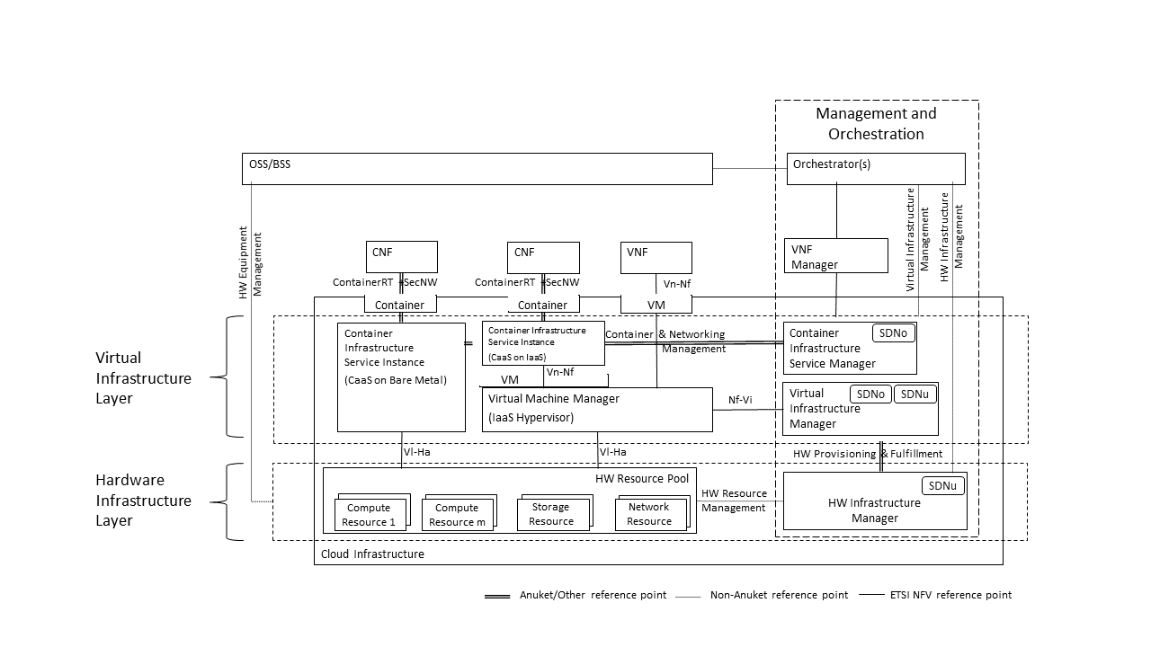
Figure 3.6 Networking Reference Model based on the ETSI NFV
3.5.4. Deployment Examples Based on the Networking Reference Model
3.5.4.1. Switch Fabric and SmartNIC Examples For Underlay Networking Separation
The HW Infrastructure Layer can implement the Underlay Networking separation in any type of packet handling component. This may be deployed in many different ways depending on target use case requirements, workload characteristics and available platforms. Two of the most common ways are: (1) within the physical Switch Fabric and (2) in a SmartNIC connected to the Server CPU being controlled over a management channel that is not reachable from the Server CPU and its host software. In either way the Underlay Networking separation is controlled by the HW Infrastructure Manager.
In both cases the Underlay Networking can be externally controlled over the SDNu interface that must be instantiated with appropriate Underlay Networking separation for each of the Virtualization administrative domains.
Note: The use of SmartNIC in this section is only pertaining to Underlay Networking separation of Virtual instances in separate Overlay domains in much the same way as AWS do with their Nitro SmartNIC. This is the important consideration for the Reference Model that enables multiple implementation instances from one or several Reference Architectures to be used on a shared Underlay Network. The use of SmartNIC components from any specific Virtual instance e.g. for internal virtual switching control and acceleration must be regulated by each Reference Architecture without interfering with the authoritative Underlay separation laid out in the Reference Model.
Two exemplifications of different common HW realisations of Underlay Network separation in the HW Infrastructure Layer can be seen in Figure 3.7 below.
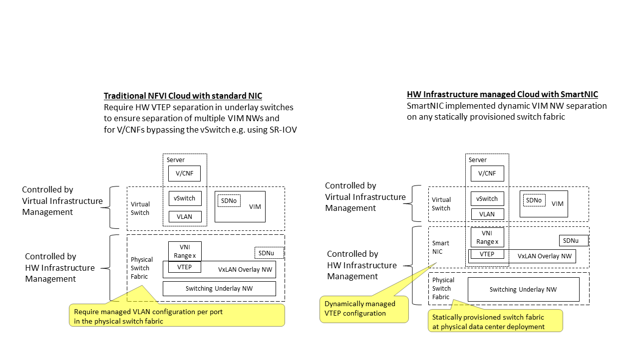
Figure 3.7 Underlay Networking separation examples
3.5.4.2. SDN Overlay and SDN Underlay layering and relationship example
Two use case examples with both SDNo and SDNu control functions depicting a software based virtual switch instance in the Virtual Infrastructure Layer and another high performance oriented Virtual Infrastructure instance (e.g. enabling SR-IOV) are described in Figure 3.8 (below). The examples are showing how the encapsulation and mapping could be done in the virtual switch or in a SmartNIC on top of a statically provisioned underlay switching fabric, but another example could also have been depicted with the SDNu controlling the underlay switching fabric without usage of SmartNICs.
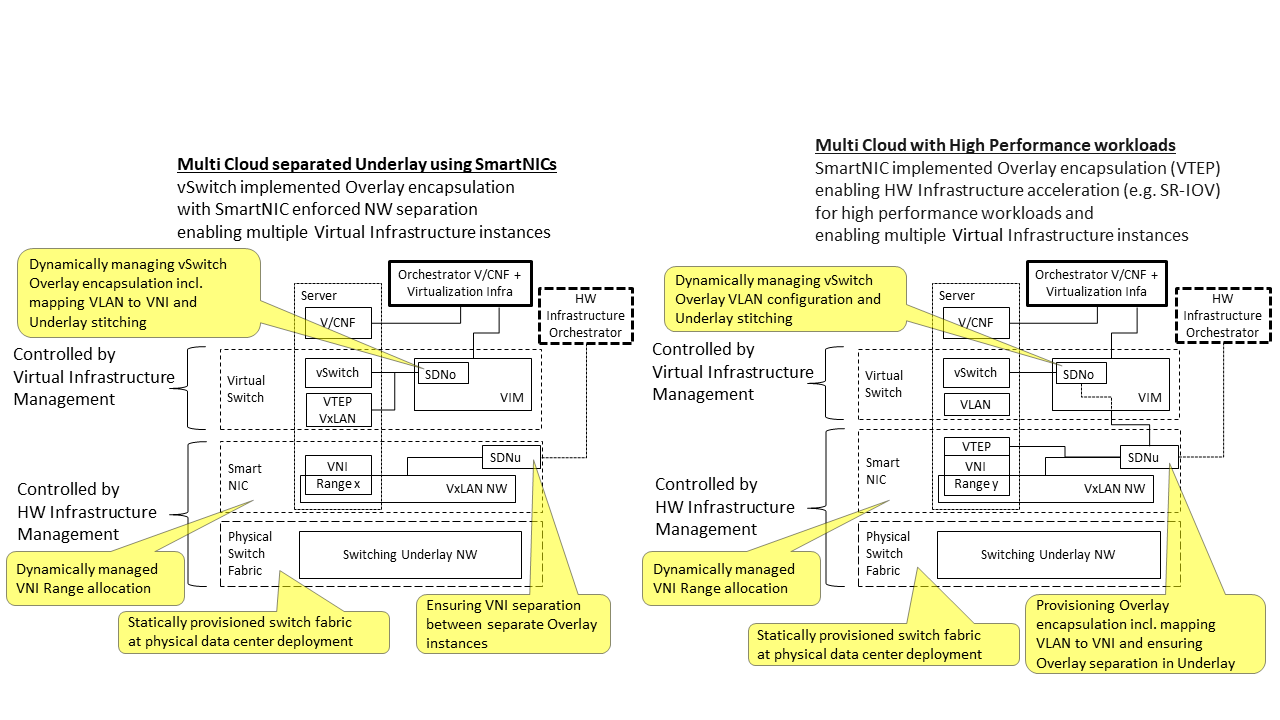
Figure 3.8 SDN Controller relationship examples
3.5.4.3. Example of IaaS and CaaS Virtualization Infrastructure Instances on a Shared HW Infrastructure With SDN
A Networking Reference Model deployment example is depicted in Figure 3.9 (below) to demonstrate the mapping to ETSI NFV reference points with additions of packet flows through the infrastructure layers and some other needed reference points. The example illustrates individual responsibilities of a complex organization with multiple separated administrative domains represented with separate colours.
The example is or will be a common scenario for operators that modernise their network functions during a rather long period of migration from VNFs to Cloud Native CNFs. Today the network functions are predominantly VNFs on IaaS environments and the operators are gradually moving a selection of these into CNFs on CaaS that either sit on top of the existing IaaS or directly on Bare Metal. It is expected that there will be multiple CaaS instances in most networks, since it is not foreseen any generic standard of a CaaS implementation that will be capable to support all types of CNFs from any vendor. It is also expected that many CNFs will have dependencies to a particular CaaS version or instances which then will prohibit a separation of Life Cycle Management in between individual CNFs and CaaS instances.
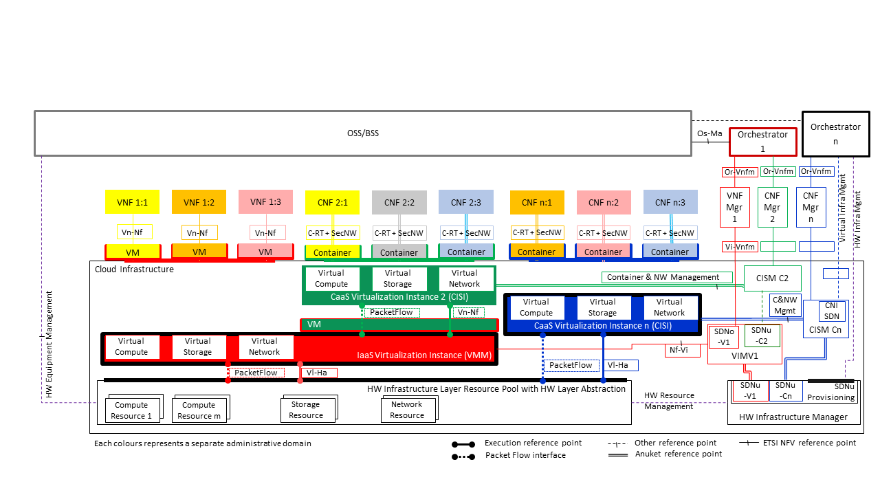
Figure 3.9 Networking Reference Model deployment example
3.5.5. Service Function Chaining
Over the past few years there has been a significant move towards decomposing network functions into smaller sub-functions that can be independently scaled and potentially reused across multiple network functions. A service chain allows composition of network functions by passing selected packets through multiple smaller services.
In order to support this capability in a sustainable manner, there is a need to have the capability to model service chains as a high level abstraction. This is essential to ensure that the underlying connection setup, and (re-)direction of traffic flows can be performed in an automated manner. At a very high level a service chain can be considered a directed acyclic graph with the composing network functions being the vertices. Building on top of this, a service chain can be modelled by defining two parameters:
An acyclic graph defining the service functions that need to be traversed for the service chain. This allows for multiple paths for a packet to traverse the service chain.
A set of packet/flow classifiers that determine what packets will enter and exit a given service chain
These capabilities need to be provided for both virtualised and containerised (cloud-native) network functions as there will be a need to support both of them for the foreseeable future. Since virtualised network functions have existed for a while there is existing, albeit partial, support for service chaining in virtualised environments in orchestration platforms like OpenStack. Container orchestration platforms such as Kubernetes don’t support service chaining and may require development of new primitives in order to support advanced networking functions.
It is expected that reference architectures will provide a service chain workflow manager that would accept the service function acyclic graph and be able to identify/create the necessary service functions and the networking between them in order to instantiate such a chain.
There is also a need to provide specialised tools to aid troubleshooting of individual services and the communication between them in order to investigate issues in the performance of composed network functions. Minimally, there is a need to provide packet level and byte level counters and statistics as the packets pass through the service chain in order to ascertain any issues with forwarding and performance. Additionally, there is a need for mechanisms to trace the paths of selected subsets of traffic as they flow through the service chain.
3.5.5.1. Service Function Chaining Model Introduction
Service Function Chaining (SFC) can be visualized as a layered structure where the Service Function plane (SFC data plane, consists of service function forwarder, classifier, service function, service function proxy) resides over a Service Function overlay network. SFC utilizes a service-specific overlay that creates the service topology. The service overlay provides service function connectivity built “on top” of the existing network topology. It leverages various overlay network technologies (e.g., Virtual eXtensible Local Area Network (VXLAN)) for interconnecting SFC data-plane elements and allows establishing Service Function Paths (SFPs).
In a typical overlay network, packets are routed based on networking principles and use a suitable path for the packet to be routed from a source to its destination.
However, in a service-specific overlay network, packets are routed based on policies. This requires specific support at network level such as at CNI in CNF environment to provide such specific routing mechanism.
3.5.5.2. SFC Architecture
The SFC Architecture is composed of functional management, control and data components as categorised in the Table 3-6 below.
The table below highlights areas under which common SFC functional components can be categorized.
Components |
Example |
Responsibilities |
|---|---|---|
Management |
|
High Level of orchestrator Orchestrate the SFC based on SFC Models/Policies with help of control components. |
|
Responsible for SFC OAM functions |
|
|
NFVO, VNFM, and VIM Responsible for SFC Data components lifecycle |
|
|
CNF DevOps Components Responsible for SFC data components lifecycle |
|
Control |
|
SDNC responsible to create the service specific overlay network. Deploy different techniques to stitch the wiring but provide the same functionality, for example l2xconn, SRv6 , Segment routing etc. |
|
Creates and wires ports/interfaces for SF data path |
|
Data |
|
Responsible for steering the traffic for intended service functionalities based on Policies |
Table 3-6: SFC Architecture Components
Note: These are logical components and listed for their functionalities only.
The SFC Architecture components can be viewed as:-
Figure 3.10 shows a simple architecture of an SFC with multiple VNFs, as SF data plane components, along with SFC management and NFV MANO components.
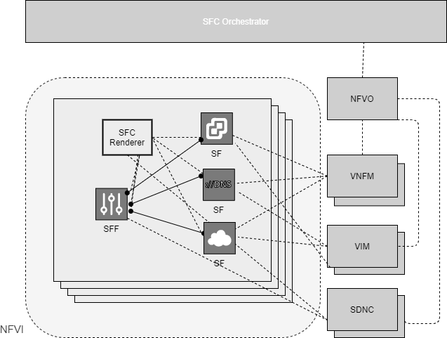
Figure 3.10 SFC Architecture for VNF based SFs
Figure 3.11 shows a simple architecture of an SFC with multiple CNFs, as SF data plane components, along with SFC management and CNF MANO components.
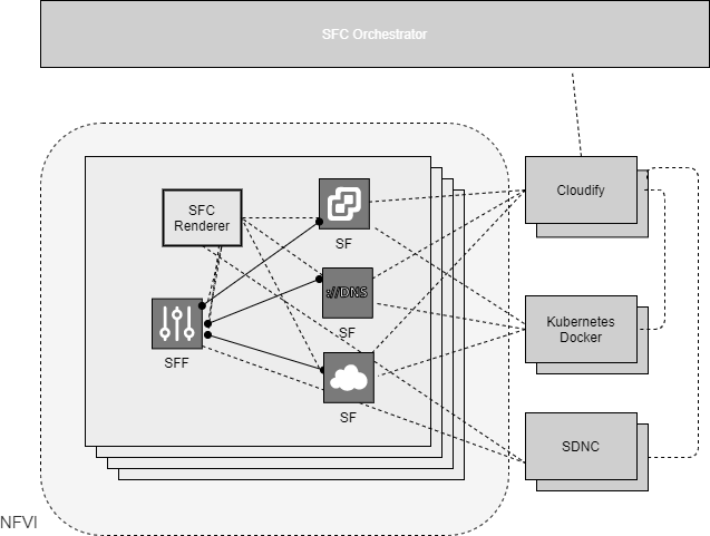
Figure 3.11 SFC Architecture for CNF based SFs
The SFC management components together with the control components are responsible for rendering SFC requests to Service Function paths. For this they convert requisite SFC policies into network topology dependent paths and forwarding steering policies. Relevant SFC data components - classifiers, service function forwarders - are responsible for managing the steering policies.
3.5.5.3. Information Flows in Service Function Chaining
3.5.5.3.1. Creation of Service Function Chain
The creation of the SFC might include design/preparation phase as:
The service functions that are included in the SFC.
The routing order in the service function, if the SFC is composed of more than one service function.
Figure 3.12 shows SFC creation call flow, separated logically in two steps.
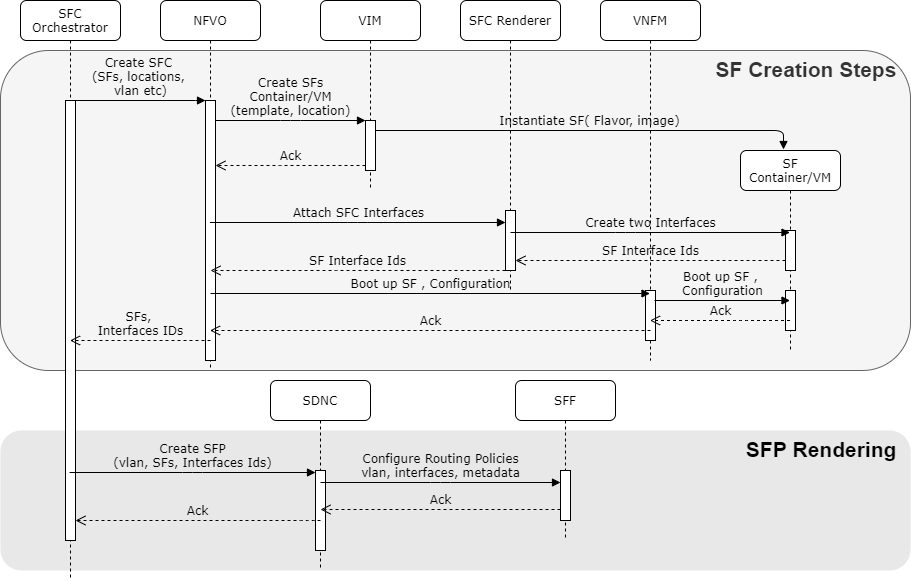
Figure 3.12 Creation of Service Function Chain
Creation of service functions of SFC.
The flow of steps to enable the SFC creation can be as follows:
SFC orchestrator creates the SFs with help of VNF MANO or CNF MANO.
SFC Renderer attaches the SFC aware interfaces at SFs to enable Service plane
NFVO boots up the relevant SF configurations at SF.
Note: These steps are optional, if SFC orchestrator discovers that SFs are already created and existing.
Creation of Service Function Path (SFP) using the created SFs and associated interfaces.
A Service Function Path consists of:
A set of ports( in VNF environment) or interfaces ( in CNF environment) , that define the sequence of service functions
A set of flow classifiers that specify the classified traffic flows entering the chain.
This step creates a new chain policy with chain rules. Chain rules can include the identifier of a traffic flow, service characteristics, the SFC identifier and related information to route the packets along the chain. Service characteristics can be application layer matching information (e.g., URL). Traffic flow identifier can be kind of traffic (e.g., Video, TCP, HTTP) flow need to be serviced. It can be specific Subscriber to apply service (e.g., parental control). The SFC identifier to steer the matched traffic along the SFP with SFC encapsulation.
SFC orchestrator creates SFP with help of SDNC.
SDNC pushes the SFC traffic steering policies to SFF(s).
SFC classifier Policy provided for SFP to SFC classifier by SFC Controller. Note: not shown in call flow.
3.5.5.3.2. Updating Service Function Chain
SFP or SFC can be updated for various reasons and some of them are:
SFC controller monitors the SFP status and alerts SFC controller in case of not meeting SLA or some anomaly.
SFC design changes to update SF order, inclusion/removal of SFs
SFC Policy Rules changes
3.5.5.3.3. Data Steering in Service Function Chain
Figure 3.13 shows traffic steering along SFP.
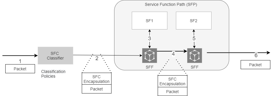
Figure 3.13 Data steering in Service Function Chain
SFC classifier detects the traffic flow based on classification policies. For example, to enable SGi-Lan feature as SFC, 5G User plane function (UPF) acts as SFC classifier. UPF receives the classification policies from 5G Policy control function (PCF) as traffic steering policies.
SFC classifier applies the SFC encapsulation (e.g., SCH, NSH) and routes traffic towards SFF, acts as entry point to SFP. The SFC Encapsulation provides, at a minimum, SFP identification, and is used by the SFC-aware functions, such as the SFF and SFC-aware SFs.
SFF based on SFC encapsulation routes the traffic to SF for service functionalities.
SF updates the SFC encapsulation based on its policies for further services.
At end of SFP, SFC encapsulation is removed and packet is routed out of SFP.
3.5.6. Time Sensitive Networking
Many network functions have time sensitivity for processing and require high precision synchronized clock for the Cloud Infrastructure. Subset of these workloads, like RAN, in addition require support for Synchronous Ethernet as well.
Reason for using Synchronous Precision Clock |
Example |
Comment |
|---|---|---|
Achieve technical requirements |
Strict latency or timing accuracy |
Must be done for precise low latency communication between data source and receiver |
Achieve technical requirements |
Separation of processing pipeline |
Ability to separate RAN into RU, DU, CU on different or stretch clusters |
Table 3-7: Reasons and examples for Precise Clock and Synchronization
Precise Synchronization require specialized card that can be on server or network device motherboard or be part of NIC or both.
OpenStack and Kubernetes clusters use Network Time Protocol (NTP) (Protocol and Algorithms Specification[27], Autokey Specification[28], Managed Objects[29], Server Option for DHCPv6[30]) as the default time synchronization for the cluster. That level of synchronization is not sufficient for some network functions. Just like real-time operating systems instead of base OS, so is precision timing for clock synchronization. Precision Time Protocol version 2 PTP[31] is commonly used for Time-Sensitive Networking. This allow synchronization in microsecond range rather than millisecond range that NTP provides.
Some Network functions, like vDU, of vRAN, also require SyncE[32]. Control, User and Synchronization (CUS) Plane specification defines different topology options that provides Lower Layer Split Control plane 1-4 (LLS-C1 - LLS-C4) with different synchronization requirements (ITU-T G.8275.2[33]).
SyncE was standardized by the ITU-T, in cooperation with IEEE, as three recommendations:
ITU-T Rec. G.8261 that defines aspects about the architecture and the wander performance of SyncE networks
ITU-T Rec. G.8262 that specifies Synchronous Ethernet clocks for SyncE
ITU-T Rec. G.8264 that describes the specification of Ethernet Synchronization Messaging Channel (ESMC) SyncE architecture minimally requires replacement of the internal clock of the Ethernet card by a phase locked loop in order to feed the Ethernet PHY.
3.5.7. Kubernetes Networking Semantics
The support for traditional network orchestration is non existent in Kubernetes as it is foremost a Platform as a Service (PaaS) environment and not an Infrastructure as a Service (Iaas) component. There is no network orchestration API, like Neutron in OpenStack, and there is no way to create L2 networks, instantiate network services such as L3aaS and LBaaS and then connect them all together as can be done using Neutron.
Kubernetes networking can be divided into two parts, built in network functionality available through the pod’s mandatory primary interface and network functionality available through the pod’s optional secondary interfaces.
3.5.7.1. Built in Kubernetes Network Functionality
Kubernetes currently only allows for one network, the cluster network, and one network attachment for each pod. All pods and containers have an eth0 interface, this interface is created by Kubernetes at pod creation and attached to the cluster network. All communication to and from the pod is done through this interface. To only allow for one interface in a pod removes the need for traditional networking tools such as VRFs and additional routes and routing tables inside the pod network namespace.
3.5.7.2. Multiple Networks and Advanced Configurations
Kubernetes does currently not in itself support multi networks, pod multi network attachments or network orchestration. This is supported by using a Container Network Interface multiplexer such as Multus. The Network Plumbing Working Group has produced the Kubernetes Network Custom Resource Definition De-facto Standard. This document describes how secondary networks can be defined and attached to pods.
3.6. Storage
3.6.1. Introduction
The general function of storage subsystem is to provide the persistent data store required for the delivery of a network service. In the context of Cloud Infrastructure the storage sub-system needs to accommodate needs of: the tenanted applications and the platform management. Each of:
underlying compute host boot and virtual machine hosting,
control plane configuration and management plane storage for fault and performance management and automation, capacity management and reporting and
tenant application and VNF storage needs
have common and specific needs for storage in terms of performance, capacity and consumption models.
The combination of common but diverse needs in conjunction with the differences in the hosting environments (from large data-centres to small edge deployments) has resulted in the proliferation of storage technologies and their deployment architectures. To address this the “Reference Model” outlines a “General Cloud Storage Model” (see Figure 3.14 - “General Cloud Storage Model”). The model will outline the different types of storage technologies and how they can be used to meet the need for:
providing storage via dedicated storage systems,
multi-tenant cloud storage,
Control and Management Plane storage needs,
across both large data-centres and small edge deployments; the model can then be used for implementing Reference Architectures.
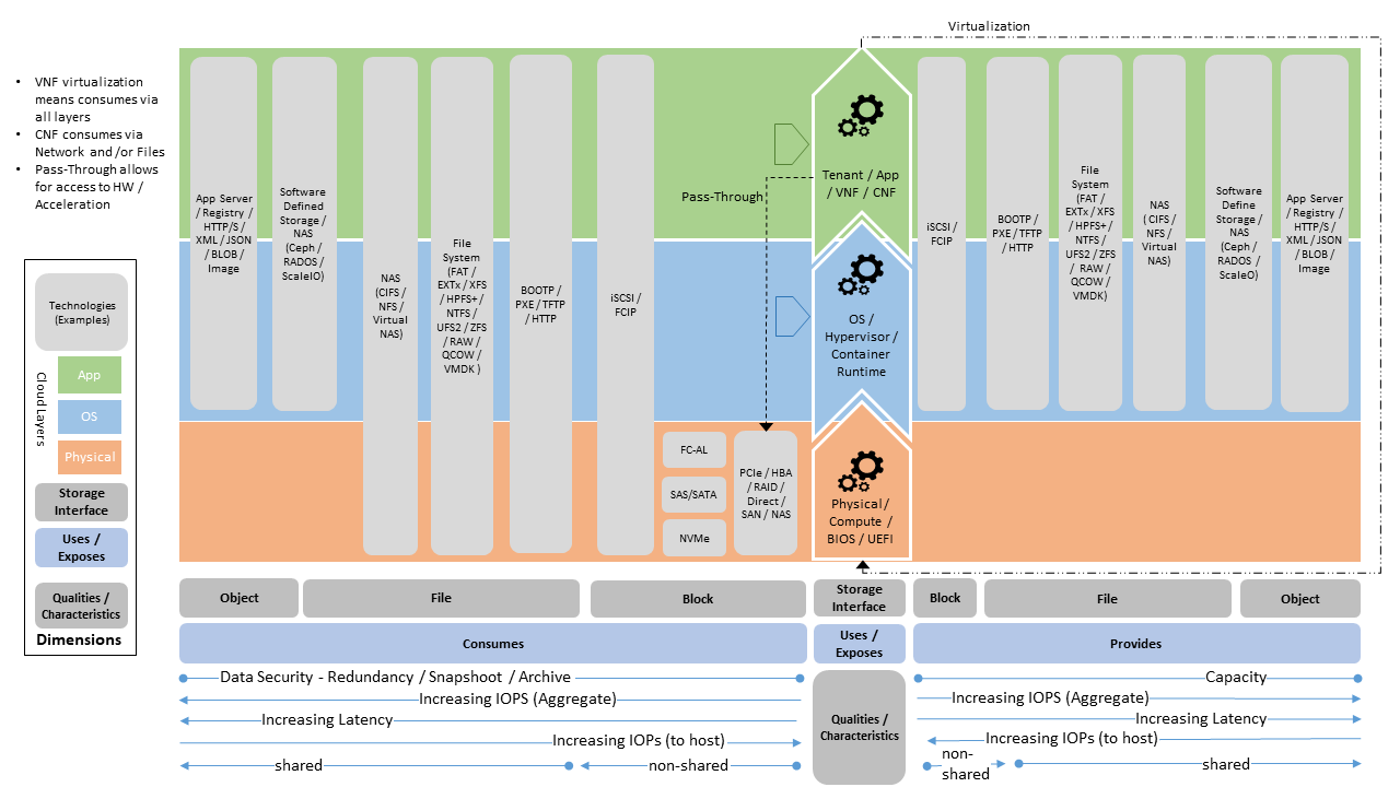
Figure 3.14 General Cloud Storage Model
Storage is multi-faceted and so can be classified based on its: cost, performance (IOPS, throughput, latency), capacity and consumption model (platform native, network shared, object or archival) and the underlying implementation model (in chassis, software defined, appliance). The objective of the model and set of stereotypes and perspectives is to provide guideance to architects and immplementors in establishing storage solutions for Cloud Infrastructure.
The following principles apply to Storage scope for the Reference Model, Reference Architectures, Reference Implementations and Reference Conformance test suites:
Abstraction: A standardized storage abstraction layer between the Virtualisation Layers and the Storage Physical Resources Layer that hides (or abstracts) the details of the Storage Physical resources from the Virtualisation Layers.
Agnosticism: Define Storage subsystem concepts and models that can provide various storage types and performance requirements (more in Virtual Resources 3.2.1.3 Storage).
Automation: Enable end-to-end automation, from Physical Storage installation and provisioning to automation of workloads (VNF/CNF) onboarding.
Openness: All storage is based on open source or standardized APIs (North Bound Interfaces (NBI) and South Bound Interfaces (SBI)) and should enable integration of storage components such as Software Defined Storage controllers.
Scalability: Storage model enables scalability to enable small up to large deployments.
Workload agnostic: Storage model can provide storage functionality to any type of workloads, including: tenant VNF, CNF and Infrastructure Management whether this is via BareMetal or Virtualised Deployments.
Operationally Amenable: The storage must be amenable to consistent set of operational processes for: Non-Disruptive Capacity Expansion and Contraction, Backup/Restoration and Archive and Performance Management. Where applicable (examples are: Backup/Restoration/Archive) these processes should also be able to be provided to tenants for their own delegated management.
Security Policy Amenable: The storage sub-systems must be amenable to policy based security controls covering areas such as: Encryption for Data at Rest / In Flight, Delegated Tenant Security Policy Management, Platform Management Security Policy Override, Secure Erase on Device Removal and others
Future proof: Storage model is extendible to support known and emerging technology trends covering spectrum of memory-storage technologies including Software Defined Storage with mix of SATA- and NVMe-based SSDs, DRAM and Persistent Memory, integrated for multi-clouds, and Edge related technologies.
The above principles should be understood as storage specific specialisations of the Anuket General Principles.
3.6.2. Storage Implementation Stereotypes
The following set of storage implementations outline some of the most prevalent stereotypical storage implementations.
The first of these are for Data Centre Storage cases, with stereotypes of:
Dedicated storage appliance (Figure 3.15) - that provide network based storage via iSCSI (2), NFS/CIFS (3) with potentially virtual NAS (vNAS) (4) capability. Having virtual network software (4) allows the establishment of storage tenancies, where storage tenancy have their own virtual storage services which are exposed on their own network,
Software defined storage (Figure 3.16) - which is able to provide similar capabilities as the dedicated storage appliance (see (3),(4) & (5) in diagram). In this case this is provided as a software solution on top of a hyper-converged infrastructure.
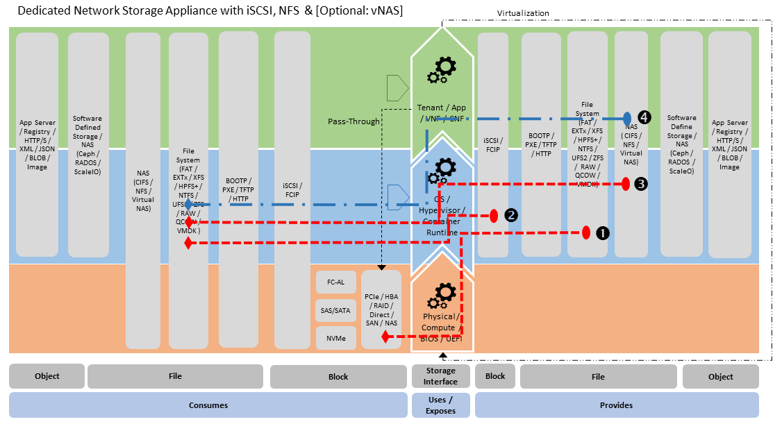
Figure 3.15 Storage Appliance Stereotype
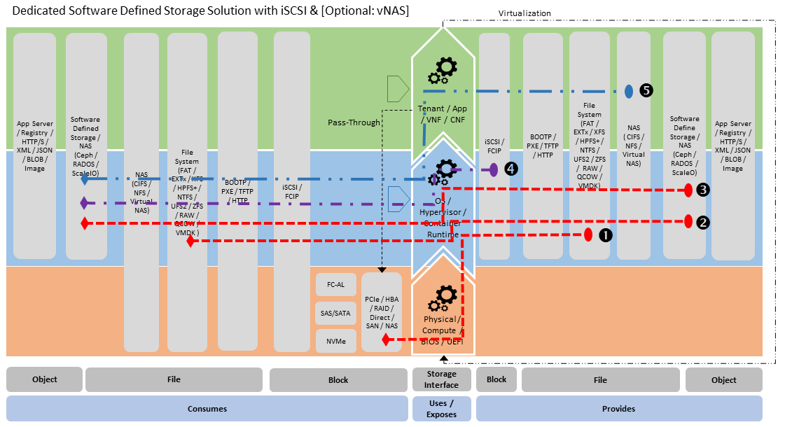
Figure 3.16 Software Defined Storage Stereotype
Both of these stereotypes can be used to support very broad storage needs from: machine boot (via iSCSI), providing storage to the Cloud Platform Control and Management Planes, Platform Native (viz., Hypervisor Attached and Container Persistence storage, as defined in section “3.6.3 Storage for Tenant Consumption”) and Application/VNF/CNF managed network storage. To provide this requires connectivity within the Cloud Infrastructure Underlay and Tenant Overlay networks.
Successful management of Cloud Infrastructure requires high levels of automation, including the ability to rapidly stand up new storage and hosting infrastructure. This Cloud Infrastructure boot-strapping process is managed through Infrastructure Automation tooling. A typical part of the boot-strap process is to use PXE boot to manage the deployment of initial images to physical hosts and a similar approach is used for “Bare Metal-as-a-Service” provisioning. The storage stereotype that covers this use case is:
Infrastructure Automation (Figure 3.17) - where PXE Boot Server provides a cache of boot images that are stored in local storage (2) which are then conditionally served up as PXE boot images (3). The PXE boot server can run within bootstrap management hosting in data-centre or within the routing / switch layer for an edge deployment case aimed to minimise physical footprint. The Infrastructure Automation PXE server is aware of the provisioning status of the physical infrastructure and will serve specific images or even not respond to PXE boot requests for hosts which have already been provisioned and are considered “in service”.
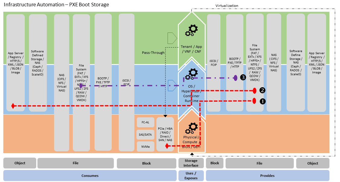
Figure 3.17 Infrastructure Automation - PXE Boot Server Stereotype
To provide PXE boot service to the underlying resource hosts, the PXE server must be connected to the same network as the NIC that is configured for PXE boot. The “Infrastructure Automation - PXE Server” stereotype is also applicable to booting tenant Virtual Machines. In this case the PXE server is on the same network as one of the machines vNICs. For tenant use this is provided as part of tenant consumable boot infrastructure services.
For each of the defined stereotypes, the storage service uses physical Block storage for boot (Physical Layer - Block Consumption -> OS File Systems Exposure (1) on stereotype diagrams). This is the primary use case for use of in chassis physical storage, that is not being used for consumption and exposure as network-based storage. In general it is desirable to use network based storage solution for provision of Cloud Infrastructure storage. The “Infrastructure Automation - PXE Server” is an exception to preference for use use of network based storage, as it is managing the bootstrap process, so it cannot be dependent on a separate storage system for maintaining its image cache.
3.6.3. Storage for Tenant Consumption
Storage is made avaiable for tenant consumption through a number of models. A simplified view of this is provided in the following illustrative model.
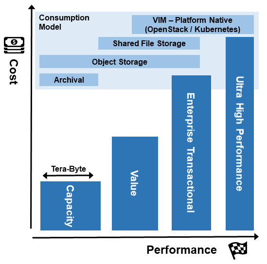
Figure 3.18 Storage Model - Cost vs Performance with Consumption Model Overlay
Where:
(Comparative) Cost - is monetary value / unit of end user storage capacity
Performance - is defined by IOPS / Latency / Throughput as typically each of these increases with successive generations of storage
Capacity - consumption needs are represented by width of the: Ultra High Performance, Enterprise Transactional, Value and Capacity storage options.
Storage Types - is how the storage is accessed and used, where:
Platform Native - is managed by the hypervisor / platform (examples are a virtual disk volume from which a VNF boots and can write back to, the storage interface that is exposed by the container runtime), this storage is typically not shared across running VNF / CNF instances;
Shared File Storage - is storage that is accessed through a file systems interface (examples are network based storage such as CIFS or NFS) where the storage volumes can be accessed and shared by multiple VNF / CNF instances;
Object Storage - is storage that is accessed via API interfaces (the most common example being HTTP restful services API), which support get/put of structured objects; and
Archival - is storage that is targeted for provision of long term storage for purpose of disaster recovery, meeting legal requirements or other historical recording where the storage mechanism may go through multiple stages before landing at rest.
The storage model provides a relatively simple way for the storage consumer to specify / select their storage needs. This is shown in the following table which highlights key attributes and features of the storage classes and “epic use cases” for common usage patterns.
Storage Type |
Consumption Model |
Performance & Capacity |
Cost |
Infrastructure Strategy |
Use Case |
|---|---|---|---|---|---|
Platform Native |
Managed by the VIM / Hypervisor and attached as part of VNF/CNF start up via VNF Descriptor, Volumes shareability across VNF/CNF instances is determined by platform and storage capabilities |
Ultra High Performance & Very High Performance, Capacity: 10GB - 5TB, “Tier 1” |
High to Very High |
Always part of VIM deployment, Storage is directly next to vCPU, Can support highest performance use cases, Always available to support VNF/CNF boot/startup |
Boot/Start VNF/CNF, Live Migrate Workload within and across VIMs |
Shared File Storage |
Access via Network File System, Concurrent consumption across multiple VNF/CNFs, Sharing can be constrained to tenancy, cross tenancy and externally accessible |
Enterprise Transactional Performance (real time transaction processing), Capacity: 5GB - 100TB, Selectable “Tier 1” to “Tier 3” |
High - Mid |
Leverage existing capabilities, Only build if needed (this is not needed by many data plane VNF/CNFs), If needed for Edge deployment then aim to unify with “Platform Native” deployment |
VNF/CNF’s able to share the same file content |
Object Storage |
Consumed via HTTP/S restful services, Provided by serving application which manages storage needs, Location Independent |
Highly distributable and scalable |
High to Mid |
Primarily tenant application responsibility |
Cloud Native Geo-Distributed VNF/CNFs |
Capacity |
Typically accessed as per “Shared Storage” but will likely have additional storage stages, Not suitable for real time processing |
Very low transactional performance, Need throughput to accommodate large data flow, “Tier 3” |
Low |
Use cheapest storage available that meets capacity & security needs |
Archival storage for tenant/platform backup/restore, DR |
Table 3-8: Tenant Storage Types
In section “3.6.2 Storage Implementation Stereotypes” the General Cloud Storage Model is used to illustrate the provision of storage. The model can also be used to illustrate the consumption of storage for use by Tenants (see below for “Platform Native” stereotypes):
Platform Native - Hypervisor Attached Consumption Stereotype (Figure 3.19) - where hypervisor consumes Software Defined Storage via Network (RA-1 - Cinder backend (2)) and the Block Image is attached to Virtual Machine (RAW or QCOW file within File System), which is used for boot and exposure to virtual machine OS as Block Storage (3). The virtual machine OS in turn consumes this for use by Tenant Application via File System,
Platform Native - Container Persistent Consumption Stereotype (Figure 3.20) - is simpler case with Container Runtime consuming Software Defined Storage (via RADOS backend (2)) and exposes this to Container as a file system mount (3).
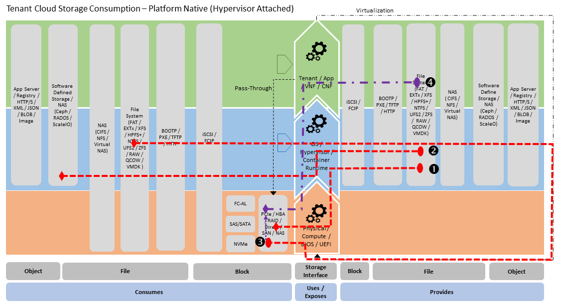
Figure 3.19 Platform Native - Hypervisor Attached Consumption Stereotype
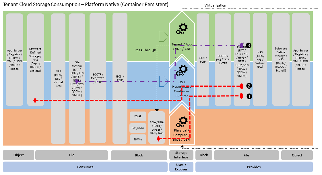
Figure 3.20 Platform Native - Container Persistent Consumption Stereotype
Note that a sterotype for Network File Storage consumption is not illustrated as this is simply managed by the Tenant Application by doing a file systems mount.
In cloud infrastructure, the storage types may manifest in various ways with substantive variations in the architecture models being used. Examples of this are provided in section “3.6.2 Storage Implementation Stereotypes”, with stereotypes for “Dedicated Storage Appliance” and “Software Defined Storage”. In the consumption case, again there is use of in-chassis storage to support hypervisor and container host OS/Runtime boot, not for Tenant / User Plane storage consumption.
3.6.4. Storage Scenarios and Architecture Fit
The storage model and stereotypical usage scenarios illustrate the key storage uses cases and their applicability to support storage needs from across a range of cloud deployments. This set of storage uses cases is summarised in the following tables, including how the stereotypes can support the Anuket Reference Architectures, followed by the key areas for consideration in such a deployment scenario. The structure of the table is:
Use Case - what is the target storage use case being covered (large data-centre, small data-centre, standalone cloud, edge etc.)
Sterotype - which of defined stereotypes is used
Infra / Ctrl / Mgt - is the storage stereotype able to support the: Infrastructure, Control Plane and Management Plane Needs
Tenant / User - is the storage stereotype able to support Tenant / User Plane needs including: Platform Native, Shared File Storage & Object Storage (as per section - “3.6.3 Storage for Tenant Consumption”)
Where:
“Y” - Yes and almost always provided
“O” - Optional and readily accommodated
“N” - No, not available
“NA” - Not Applicable for this Use Case / Stereotype
Tenant / User |
|||||||||||
|---|---|---|---|---|---|---|---|---|---|---|---|
Infra / Ctrl / Mgt |
Platform Native |
Shared File |
Object |
||||||||
Use Case |
Stereotype |
Boot |
Ctrl |
Mgt |
Hypervisor Attached |
Container Persistent |
Within |
Cross |
Ext |
vNAS |
Object |
Data-centre Storage |
Dedicated Network Storage Appliance |
Y |
Y |
Y |
Y |
Y |
O |
O |
O |
O |
O |
Dedicated Software Defined Storage |
O |
O |
O |
Y |
Y |
O |
O |
O |
O |
O |
|
Traditional SAN |
Y |
Y |
Y |
N |
N |
N |
N |
N |
N |
N |
|
Satelite data-centre Storage |
Small Software Defined Storage |
O |
O |
O |
Y |
Y |
O |
O |
O |
O |
O |
Small data-centre Storage |
Converged Software Defined Storage |
O |
O |
O |
Y |
Y |
O |
O |
O |
O |
O |
Edge Cloud |
Edge Cloud for VNF/CNF Storage |
NA |
O |
NA |
Y |
Y |
O |
O |
O |
O |
O |
Edge Cloud for Apps Storage |
NA |
O |
NA |
Y |
Y |
O |
O |
O |
O |
Y |
|
Edge Cloud for Content Mgt Storage |
NA |
O |
NA |
Y |
Y |
O |
O |
O |
O |
Y |
Table 3-9: Storage Use Cases and Stereotypes
The storage sub-system is a foundational part of any Cloud Infrastructure, as such it is important to identify the storage needs, based on target tenant use cases, at inception. This will allow the right set of considerations to be addressed for the deployment. A set of typical considerations is provided for various use cases to meet functional and performance needs and to avoid the need for signifiant rework of the storage solution and its likely ripple through impact on the broader Cloud Infrastructure. The considerations will help to guide the build and deployment of the Storage solution for the various Use Cases and Stereotypes outlined in the summary table.
Data-centre Storage - in data-centre the goal is to provide a storage capability that has the flexibility to meet the needs of:
Cloud Infrastructure Control Plane (tenant Virtual Machine and Container life-cycle management and control),
Cloud Infrastrastructure Management Plane (Cloud Infrastructure fault and performance management and platform automation) and
Cloud Infastructure Tenant / User Plane,
General Areas of Consideration:
Can storage support Virtual Machine (RA-1) & Container (RA-2) Hosting cases from single instance? Noting that if you wish to have single storage instance providing storage across multiple clusters / availability zones within the same data-centre then this needs to be factored into the underlay network design.
Can the storage system support Live Migration / Multi-Attach within and across Availability Zones (applicable to Virtual Machine hosting (RA-1)) and how does the Cloud Infrastructure solution support migration of Virtual Machines between availability zones in general?
Can the storage system support the full range of Shared File Storage use cases: including the ability to control how network exposed Share File Storage is visible: Within Tenancy, Across Tenancy (noting that a Tenancy can operate across availability zones) and Externally?
Can the storage system support alternate performance tiers to allow tenant selection of best Cost/Performance option? For very high performance storage provision, meeting throughput and IOP needs can be achieved by using: very high IOP flash storage, higher bandwidth networking, performance optimised replication design and storage pool host distribution, while achieving very low latency targets requires careful planning of underlay storage VLAN / switch networking.
Specific Areas of Consideration:
Dedicated Software Defined Storage:
Need to establish the physical disk data layout / encoding scheme choice, options could be: replication / mirroring of data across multiple storage hosts or CRC-based redundancy management encoding (such as “erasure encoding”). This typically has performance / cost implications as replication has a lower performance impact, but consumes larger number of physical disks. If using replication then increasing the number of replicas provide greater data loss prevention, but consumes more disk system backend network bandwidth, with bandwidth need proportional to number of replicas.
In general with Software Defined Storage solution it is not desirable to use hardware RAID controllers, as this impacts the scope of recovery on failure as the failed device replacement can only be managed within the RAID volume that disk is part of. With Software Defined Storage failure recovering can be managed within the host that the disk failed in, but also across phyiscal storage hosts.
Can storage be consumed optimally irrespective of whether this is at Control, Management or Tenant / User Plane? Example is iSCSI / NFS, which while available and providing a common technical capability, it does not provide best performance that can be achieved. This is best achieved using provided OS layer driver that matches the particular software defined storage implementation (example is using RADOS driver in Ceph case vs. Ceph ability to expose iSCSI).
Dedicated Network Storage Appliance:
Macro choice is made based on vendor / model selection and configuration choices available
Traditional SAN:
This is generally made available via FC-AL / SCSI connectivity and hence has a need for very specific connectivity. To provide the features required for Cloud Infrastructure (Shared File Storage, Object Storage and Multi-tenancy support) a SAN storage systems needs to be augmented with other gateway/s to provide an IP Network consumable capability. This is often seen with current deployments where NFS/CIFS (NAS) Gateway is connected by FC-AL (for storage back-end) and IP Network for Cloud Infrastructure consumption (front-end). This model helps to extent use of SAN storage investment. NOTE: This applys to SANs which use SAS/SATA physical disk devices, as direct connect FC-AL disk devices are no longer manufactored.
Satelite Data-centre Storage - the satelite data-centre is a smaller regional deployment which has connectivity to and utilises resources available from the main Data-centre and as such is more likely needed to support:
Cloud Infrastructure Control Plane (tenant Virtual Machine and Container life-cycle management and control) and
Cloud Infastructure Tenant / User Plane,
General Areas of Consideration:
Is there a need to support multiple clusters / availability zones at the same site? If so then use “Data-Centre Storage” use case, otherwise, consider how to put Virtual Machine & Container Hosting control plane and Storage control plane on the same set of hosts to reduce footprint.
Can Shared File Storage establishment be avoided by using capabilities provided by large Data-Centre Storage?
Can very large capacity storage needs be moved to larger Data-Centre Storage capabilities?
Specific Areas of Consideration:
Small Software Defined Storage:
Leverage same technology as “Dedicated Software Defined Storage” scenarios, but avoid / limit Infrastructure boot and Management Plane support and Network Storage support
Avoid having dedicated storage instance per cluster / availability zone
Resilience through rapid rebuild (N + 1 failure scenario)
Small Data-centre Storage - the small data-centre storage deployment is used in cases where software-defined storage and virtual machine / container hosting are running on a converged infrastructure footprint with the aim of reducing the overall size of the platform. This solution is then a standalone Infrastructure Cloud platform. This storage solution would need to support:
Cloud Infrastructure Control Plane (tenant Virtual Machine and Container life-cycle management and control) and
Cloud Infrastrastructure Management Plane (Cloud Infrastructure fault and performance management and platform automation) and
Cloud Infastructure Tenant / User Plane,
General Areas of Consideration:
Is there need to support multiple clusters / availability zones at same site? Follow guidance as per “Satelite Data-centre Storage” use case (1).
Is Shared File Storage required? Check sharing scope carefully as fully virtualised vNFS solution adds complexity and increases resources needs.
Is there need for large local capacity ? With large capacity flash (15 - 30 TB / device) the solution can hold signficant storage capacilty, but need to carefully consider data loss prevention needs and impact on rebuilt / recovery times.
Specific Areas of Consideration:
Converged Software Defined Storage:
Leverage same technology as “Dedicated Software-Defined Storage” scenarios, but on converged infrastructure. To meet capacity needs provision three hosts for storage and the rest for virtual infrastructure and storage control and management and tenant workload hosting.
If the solution needs to host two clusters / availability zones then have sharable storage instances.
Resilience through rapid rebuild (N + 0 or N + 1)
Edge Cloud for VNF/CNF Storage - this edge case is to support the deployment of VNF / CNF at the edge. The only storage needs are those required to support:
Cloud Infrastructure Control Plane (tenant Virtual Machine and Container life-cycle management and control) and
Cloud Infastructure Tenant / User Plane - very limited configuration storage
Edge Cloud for App Storage - this edge case is to support the deployment of applications at the edge. The only storage needs are those required to support:
Cloud Infrastructure Control Plane (tenant Virtual Machine and Container life-cycle management and control) and
Cloud Infrastructure Tenant / User Plane - very limited configuration storage.
Edge Cloud for Content Storage - this edge case is to support the deployment of media content cache at the edge. This is a very common Content Distribution Network use case. The only storage needs are those required to support:
Cloud Infrastructure Control Plane (tenant Virtual Machine and Container life-cycle management and control) and
Cloud Infastructure Tenant / User Plane - Media Content and
General Areas of Consideration:
Consuming and exposing Object storage through Tenant application
Use Embedded Shared File Storage for Control and Tenant Storage Needs
Specific Areas of Consideration:
Embedded Shared File Storage:
The General Storage Model illustrates that at the bottom of any storage solution there is always the physical storage layer and a storage operating system of some sort. In Cloud Infrastructure enviroment what is generally consumed is some form of network storage which can be provided by the:
Infrastructure platform underlay network for Control Plan and Platform Native - Hypervisor Attached and Container Runtime Managed
Tenant / User overlay network for Shared File Storage and Object Storage
In general for the provision of storage as shared resource it is not desirable to use “in chassis storage” for anything other than in the storage devices for platform hypervisor / OS boot or for the hosts providing the storage sub-systems deployment itself. This is due to difficulty in resulting operational management (see principles section “3.6.1 Introduction” - “Operationally Amenable” above).
For cloud based storage “Ephemeral” storage (hypervisor attached or container images which are disposed when VNF/CNF is stopped) is often distinguished from other persistent storage, however this is a behaviour variation that is managed via the VNF descriptor rather than a specific Storage Type.
Storage also follows the alignment of separated virtual and physical resources of Virtual Infrastructure Layer and HW Infrastructure Layer. Reasons for such alignment are described more in Section 3.5.
While there are new storage technologies being made available and a trend towards the use of flash for all physical storage needs, for the near future, the core storage architecture for Cloud Infrastructure is likely to remain consistent with the network-based consumption model, as described through the stereotypes.
3.7. Sample reference model realization
The following diagram presents an example of the realization of the reference model, where a virtual infrastructure layer contains three coexisting but different types of implementation: a typical IaaS using VMs and a hypervisor for virtualisation, a CaaS on VM/hypervisor, and a CaaS on bare metal. This diagram is presented for illustration purposes only and it does not preclude validity of many other different combinations of implementation types. Note that the model enables several potentially different controllers orchestrating different type of resources (virtual and/or hardware). Management clients can manage virtual resources via Virtual Infrastructure Manager (Container Infrastructure Service Manager for CaaS, or Virtual Infrastructure Manager for IaaS), or alternatively hardware infrastructure resources via hardware infrastructure manager. The latter situation may occur for instance when an orchestrator (an example of a management client) is involved in provisioning the physical network resources with the assistance of the controllers. Also, this realization example would enable implementation of a programmable fabric.
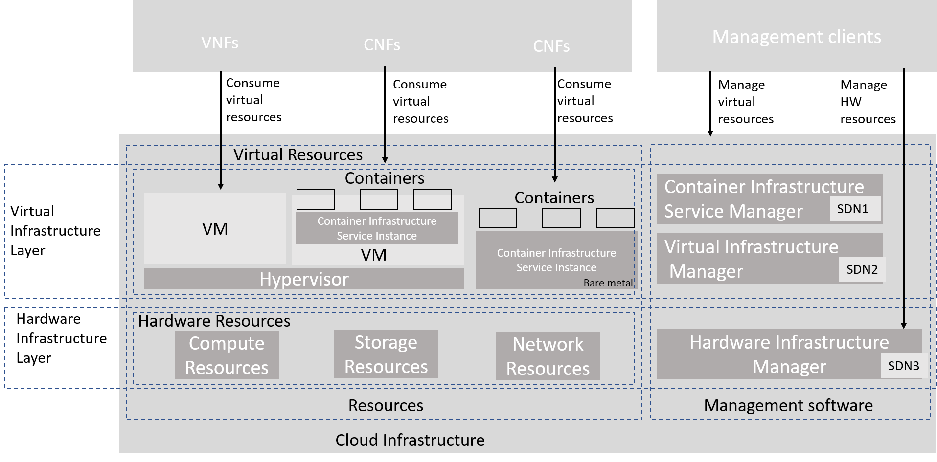
Figure 3.21 Reference model realization example
The terms Container Infrastructure Service Instance and Container Infrastructure Service Manager should be understood as defined in ETSI GR NFV-IFA 029 V3.3.1 [4]. More detailed deployment examples can be found in Network of this Reference Model document.
3.8. Hardware Acceleration Abstraction
The purpose of a Hardware Accelerator is to either Accelerate the execution of an application or to Offload functions from the generic CPU to make the application and/or Cloud Infrastructure more efficient from one or more aspects.
Hardware Accelerators are often used in Telco Clouds for many reasons. Some applications require an Hardware Accelerator to perform tasks that a generic CPU cannot perform fast enough, with enough timing accuracy, or handle the traffic that must be kept in a single context. Other applications could be satisfied with a generic CPU performance in some deployment cases, whilst being inefficient in other situations. The Cloud Infrastructure might also benefit from specialised accelerated HW devices to perform its tasks with less power, space, or cost than a generic CPU.
The Accelerators are specialized resources and generally not expected to exist in large quantities, which makes it important that these limited HW Accelerators are carefully assigned to where they can be best used most of the time. In general, this requires that there be software-based alternative functions that can be used for the occasions when HW Accelerators can not be assigned to accelerate or offload applications or Cloud Infrastructure tasks.
It is preferred that the accelerated or offloaded functions have abstracted interfaces since that would hide the different implementations from a functional point of view and make orchestrator choices simpler and more transparent to deploy. It will also allow support for multiple different HW Accelerators, and reducing the operator’s integration and test efforts of the accelerators and their applications and/or Cloud Infrastructure.
3.8.1. Types of Accelerators
Accelerator technologies can be categorized depending on where they are realized in the hardware product and how they get activated, life cycle managed and supported in running infrastructure.
Acceleration technology/hardware |
Example implementation |
Activation/LCM/support |
Usage by application tenant |
|---|---|---|---|
CPU instructions |
Within CPU cores |
None for hardware |
Application to load software library that recognizes and uses CPU instructions |
Fixed function accelerator |
Crypto, vRAN-specific adapter |
Rare updates |
Application to load software library/driver that recognizes and uses the accelerator |
Firmware-programmable adapter |
Network/storage adapter with programmable part of firmware image |
Rare updates |
Application normally not modified or aware |
SmartNIC |
Programmable accelerator for vSwitch/vRouter, NF and/or Hardware Infrastructure |
Programmable by Infrastructure operator(s) and/or application tenant(s) |
3 types/operational modes: 1. Non-programmable normally with unaware applications; 2. Once programmable to activate; 3 Reprogrammable |
SmartSwitch-based |
Programmable Switch Fabric or TOR switch |
Programmable by Infrastructure operator(s) and/or application tenant(s) |
3 operational modes: 1. Non-programmable normally with unaware applications; 2. Once programmable to activate; 3. Reprogrammable |
Table 3-10: Hardware acceleration categories, implementation, activation/LCM/support and usage
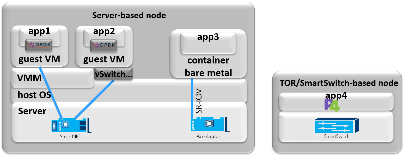
Figure 3.22 Examples of server- and SmartSwitch-based nodes (for illustration only)
3.8.2. Infrastructure and Application Level Acceleration
Figure 3.23 gives examples for the Hardware Accelerators shown in Figure 3.21 (the Sample reference model realization diagram).
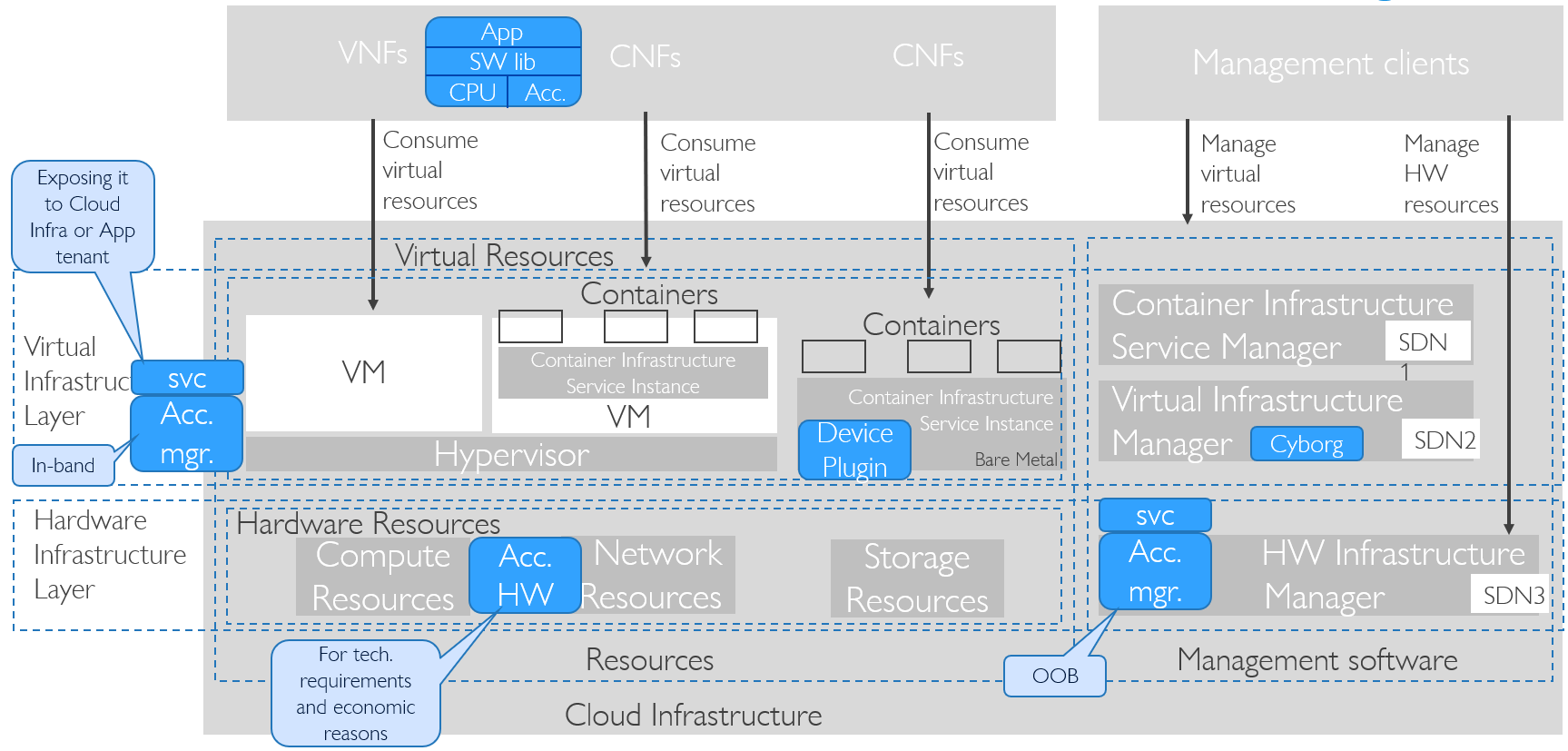
Figure 3.23 Hardware Acceleration in RM Realization Diagram
Hardware Accelerators are part of the Hardware Infrastructure Layer. Those that need to be activated/programmed will expose management interfaces and have Accelerator Management software managing them in-band (from host OS) or out of band (OOB, over some network to the adapter without going through host OS). For more flexibility in management, such Accelerator Management can be carried over appropriate service with authentication mechanism before being exposed to Cloud Infrastructure operator and/or Application tenant.
Application uses software library supporting hardware acceleration and running on generic CPU instructions. Mapping workload to acceleration hardware is done with Cyborg in OpenStack or Device Plugin framework in Kubernetes. Hardware accelerator supports both in-band and/or out of band management, with service exposing it to Cloud Infrastructure operator or Application tenant roles.
Hardware Accelerators can be used as:
Virtualization Infrastructure layer acceleration: Example can be vSwitch, which can be leveraged agnostically by VNFs if standard host interfaces (like VirtIO) are used.
Application layer acceleration: Example of software library/framework (like DPDK) in VM providing Application level acceleration with (where available) hardware-abstracted APIs to access platform Hardware Acceleration and providing software equivalent libraries when hardware assist not available.
Hardware Infrastructure layer offload: Example can be an OOB managed underlay network separation providing network separation secured from host OS reach on any provisioned transport switch infrastructure.
Two levels of consumption are for underlay separation or overlay acceleration. Underlay Separation ensures that multiple different Virtualization Infrastructure instances are kept in separate underlay network access domains. Overlay Acceleration offloads Virtualization Infrastructure instance vSwitch/vRouter or virtual termination endpoints (for applications that bypass the Virtual Infrastructure Layer).
Preferably, Application or Infrastructure acceleration can take benefit from underlying hardware acceleration and still be decoupled from it by using open multi-vendor API for Hardware Acceleration devices like for example:
For Linux IO virtualization: VirtIO
For Network Functions using DPDK libraries: Crypto Device, EthDev, Event Device and Base Band Device
For O-RAN Network functions: O-RAN Acceleration Abstraction Layer Interface.
3.8.3. Example of O-RAN Acceleration Abstraction Layer Interface
O-RAN Alliance’s Cloudification and Orchestration Workgroup (WG6) defines the Acceleration Abstraction Layer (AAL), an application-level interface, as the recommended way of decoupling software vendors’ network functions from the different hardware accelerator implementations.
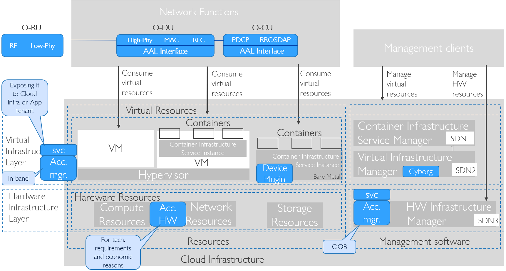
Figure 3.24 AAL Interface in RM Realization Diagram
The document “O-RAN Acceleration Abstraction Layer General Aspects and Principles 1.0” (O-RAN.WG6.AAL-GAnP-v01.00, November 2020, available to the public upon agreement to the O-RAN Alliance Adopter License, from https://www.o-ran.org):
Describes the functions conveyed over the AAL interface, including configuration and management functions.
Identifies the requirements as well as general procedures and operations.
Introduces the initial set of the O-DU/O-CU AAL profiles.
3.8.4. Workload Placement
Workload placement can be done by a combination of filters/selectors to find appropriate compute resources, subsystems to manage assignment of scheduled workloads to Hardware Accelerator, and intelligence in the workload to detect the presence of Hardware Accelerators.
For initial limited cloud deployments of network functions on private clouds it is possible to have a workload placement orchestrator that handles optimizations of selected virtualisation clusters and available hardware resources. This will however soon become too complex with the increasing number of acceleration devices, hardware composability and hybrid multi-cloud deployments.
Growing lists of individual optimizations including hardware acceleration during scheduling makes it more complex to map workloads to lists of individual optimizations, so such optimizations get grouped together into higher level categories. An example is having category for real-time and data plane-optimized category instead of specifying individual optimizations required to reach it.
With further growth in size of clusters and the variety of hardware acceleration, in a hybrid or multi-cloud deployment, it will be necessary to enable separate optimization levels for the workload placement and each Cloud Infrastructure provider. The workload placement orchestrator will operate on one or several Cloud Infrastructures resources to satisfy the workloads according to Service Level Agreements (SLA) that do not specify all implementation and resource details. Each Cloud Infrastructure provider will make internal Infrastructure optimisations towards their own internal optimisation targets whilst fulfilling the SLAs.
3.8.5. CPU Instructions
The CPU architecture often includes instructions and execution blocks for most common compute-heavy algorithms like block cypher (example AES-NI), Random Number Generator or vector instructions. These functions are normally consumed in infrastructure software or applications by using enabled software libraries that run faster when custom CPU instructions for the execution of such functions are available in hardware and slower when these specific instructions are not available in hardware as only the general CPU instructions are used. Custom CPU instructions don’t need to be activated or life-cycle-managed. When scheduling workloads, compute nodes with such custom CPU instructions can be found by applications or an orchestrator using OpenStack Nova filters or Kubernetes Node Feature Discovery labels, or directly from the Hardware Management layer.
3.8.6. Fixed Function Accelerators
Fixed function accelerators can come as adapters with in-line (typically PCIe adapter with Ethernet ports or storage drives) or look-aside (typically PCIe adapters without any external ports) functionality, additional chip on motherboard, included into server chipsets or packaged/embedded into main CPU. They can accelerate cryptographic functions, highly parallelized or other specific algorithms. Initial activation and rare life cycle management events (like updating firmware image) can typically be done from the Host OS (e.g. the OS driver or a Library), the Hardware Infrastructure Manager (from a library) or the NF (mostly through a library).
Beyond finding such compute nodes during scheduling workloads, those workloads also need to be mapped to the accelerator, both of which in Kubernetes can be done with Device Plugin framework. Once mapped to the application, the application can use enabled software libraries and/or device drivers that will use hardware acceleration. If hardware acceleration is used to improve cost/performance, then application can also run on generic compute node without hardware accelerator when application will use the same software library to run on generic CPU instructions.
3.8.7. Firmware-programmable Adapters
Firmware-programmable network adapters with programmable pipeline are types of network adapters where usual Ethernet controller functionality (accelerates common network overlays, checksums or protocol termination) can be extended with partially programmable modules so that additional protocols can be recognized, parsed and put into specific queues, which helps increase performance and reduce load on main CPU.
Firmware-programmable storage adapters can offload some of the storage functionality and include storage drive emulation to enable partial drive assignments up to the accessing host OS. These adapters can over time include more supported storage offload functions or support more drive emulation functions.
Before being used, such adapters have to be activated by loading programmable module that typically accelerates the Virtualization Infrastructure, so it is not often reprogrammed. Doing this in multivendor environments can lead to complexities because the adapter hardware is typically specified, installed and supported by server vendor while the programmable image on the adapter is managed by SDN, Storage Controller or Software Infrastructure vendor.
3.8.8. SmartNICs
Programmable SmartNIC accelerators can come as programmable in-line adapters (typically PCIe adapter with Ethernet ports), or network connected pooled accelerators like farms of GPU or FPGA where the normal CPU PCIe connection is extended with an Ethernet hop.
There are two main types of Smart NICs that can accelerate network functions in-line between CPU and Ethernet ports of servers. The simpler types have a configurable or programmable packet pipeline that can implement offload for the infrastructure virtual switching or part of an application functions data plane. The more advanced type, often called Data Processing Unit (DPU), have a programmable pipeline and some strong CPU cores that simultaneously can implement underlay networking separation and trusted forwarding functions, infrastructure virtual switching data and control plane as well as part of an application functions control plane.
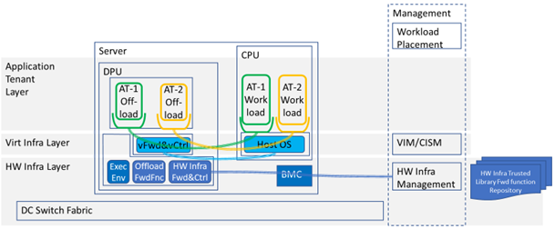
Figure 3.25 Example SmartNIC Deployment Model That Accelerates Two Workloads and Has OOB Management
3.8.8.1. Simple SmartNIC
The preferred usage of a simple SmartNIC is for the Virtualization Infrastructure usage that typically implements the data (forwarding) plane of the virtual switch or router. These deployments can offer a standardized higher-level abstract interface towards the application tenants such as VirtIO that supports good portability and is by that the preferred usage method.
Simple SmartNICs direct usage by the application tenant (VNF or CNF), where it acts as a dedicated accelerator appliance, require the application tenant to manage loading and the function that is loaded in the SmartNIC as well as any interface to the offloaded network functions. Such deployment is similar to the NIC PCI Pass-Through in that it bypasses the Virtualization Infrastructure layer’s virtual switching, which require all network encapsulation, mapping and separation to be done by the underlay network, often by manual provisioning and therefore is not a preferred usage method.
3.8.8.2. DPU
The DPU can accelerate software infrastructure functions (vSwitch/vRouter) from the main CPU and simultaneously offer networking services e.g. load balancers, firewalls and application tenant offload functions. Through Out of band management it can also ensure underlay separation and map a selected part of the underlay network to the specific Virtualization Infrastructure instance that the server it is mounted on requires allowing them to be used on any statically provisioned underlay network.
The forwarding path (data plane) needs to be installed and controlled by the Hardware Infrastructure Manager through an isolated Out of band management channel into the DPU control and operating system completely out of reach for the main CPU Host SW. All content in the forwarding path must come from Hardware Infrastructure operator trusted code since any fault or malicious content can seriously disturb the whole network for all connected devices.
The trusted forwarding functions must be handled through a Hardware Infrastructure Management repository and have APIs for their respective control functions. These APIs must have an ability to handle some version differences since the forwarding and control planes life cycle management will not be atomic. The offload functions that should be offered as services must have published and preferably standardized open APIs, but the application specific forwarding functions do not have to be open APIs since they will only communicate with the application tenant provided control functions. P4 and OpenConfig are examples of suitable languages and models, with different levels of flexibility, usable for these forwarding and control functions.
The separated management channel could either come in through the BMC, a direct management port on the DPU or through a management VPN on the switch ports. This enable the Hardware Infrastructure Management to automate its networking through the DPU without any need to dynamically manage the switch fabric, thereby enabling a free choice of switch fabric vendor. These deployments allow the switch fabric to be statically provisioned by the operators networking operation unit, as it is often required.
The DPU can offload control and data plane of the virtual switching to the DPU as well as trusted hardware offload for virtualized Packet Core and Radio data plane networking and transport related functionality in a power efficient way. It can also offload relevant application tenant control functions if the DPU offers an Execution Environment for VMs or containers and there is space and performance headroom. In such cases the DPU must also setup a communication channel into respective application tenant environment.
3.8.9. Smart Switches
Smart Switches can be broadly categorized into Configurable Switches and Programmable Switches.
Configurable Smart Switches run generic “smart” configurable network operating system offering full range of network functionality and are flexible enough to support most network solutions. The most common such network operating system is Linux-based SONiC allowing hardware and software disaggregation by running on switches from multiple switch vendors with different types of vendor fixed-function ASICs. Still, SONiC today cannot implement new type of data plane functionality or patch/modify/correct an ASIC, which is the type of support offered by programmable smart switches.
Programmable Smart Switches make it possible to quickly support new or correct/modify existing protocols and network functions, allow end customers to implement network functions, and to only implement and load functionality that is needed. Such switches contain one or more programmable switch ASICs of the same or different types. The two most used programming languages are P4 and NPL, and both can be used with vendor-specific toolchains to program their switch ASICs and/or FPGAs. Open Networking Foundation Stratum is an example of network operating system that offers generic life cycle management control services for the P4 components and a management API. The control API for the individual network functions are not part of the Stratum APIs.
Based on Smart Switches, products exist for fully integrated edge and fabric solutions from vendors like Arista, Cisco or Kaloom.
3.8.10. Decoupling Applications from Infrastructure and Platform with Hardware Acceleration
Decoupling Cloud Platform Abstraction Related Terminology: applications from hardware accelerator is normally accomplished using drivers that, if available, are preferred with standardised interfaces across vendors and their products, or if not available then through drivers specific to the vendor hardware device. Decoupling infrastructure software from hardware accelerators is also preferred using standard interfaces. If those are not available for target hardware accelerator, coupling one or limited number of software infrastructures is less of an issue compared to coupling multiple applications.
Taking advantage of RM and RA environments with common capabilities, applications can be developed and deployed more rapidly, providing more service agility and easier operations. The extent to which this can be achieved will depend on levels of decoupling between application and infrastructure or platform underneath the application:
3.8.10.1. Infrastructure:
Application functionality or application control requires infrastructure components beyond RM profiles or infrastructure configuration changes beyond APIs specified by RA. Generally, such an application is tightly coupled with the infrastructure which results in an Appliance deployment model (see Cloud Platform Abstraction Related Terminology:).
Application control using APIs specified by RA finds nodes (already configured in support of the profiles) with the required infrastructure component(s), and in that node using APIs specified by RA configures infrastructure components that make application work. Example is an application that to achieve latency requirements needs certain hardware acceleration available in RM profile and is exposed through APIs specified by RA.
Application control using APIs specified by RA finds nodes (already configured in support of the profiles) with optional infrastructure component(s), and in these nodes using APIs specified by RA configures infrastructure component(s) that make application work better (like more performant) than without that infrastructure component. Example is an application that would have better cost/performance with certain acceleration adapter but can also work without it.
Application control using APIs specified by RA finds general profile nodes without any specific infrastructure components.
3.8.10.2. Platform Services:
Application functionality or application control can work only with its own components instead of using defined Platform Services. Example is an application that brings its own Load Balancer.
With custom integration effort, application can be made to use defined Platform Services. Example is application that with custom integration effort can use defined Load Balancer which can be accelerated with hardware acceleration in way that is fully decoupled from application (i.e. application does not have awareness of Load Balancer being hardware-accelerated).
Application is designed and can be configured for running with defined Platform Services. Example is application that can be configured to use defined Load Balancer which can be accelerated with hardware acceleration.